Hi, I'm Tom. Welcome to our shop,
Carymart offers you the premium rf remote control equipment.
We suggest you reading our FAQs before making your decision.
If you have any other question, please contact us.
We will reply you as soon as possible.
Application:
Mainly used for doors, windows, cellars, trapdoors, hatchways, solar
tracking system, medical devices, agricultural machinery, vehicles, ships,
elevator platforms, lifting tables, TV lifts, robots, cabinetries, massage
sofas, electric beds, medical chairs, and other electrical equipment. It can
open, close, push, pull, lift, and descend these devices.
It can replace hydraulic and pneumatic products to save power consumption.
Feature:
High-quality products and high-quality services
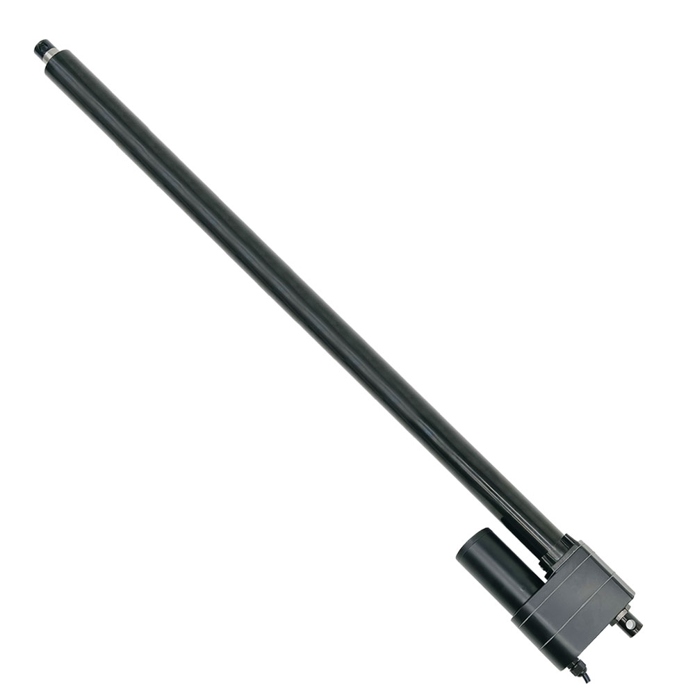
Metal housing, able to work in very harsh environments
Metal gearbox and high strength wear-resistant metal gears
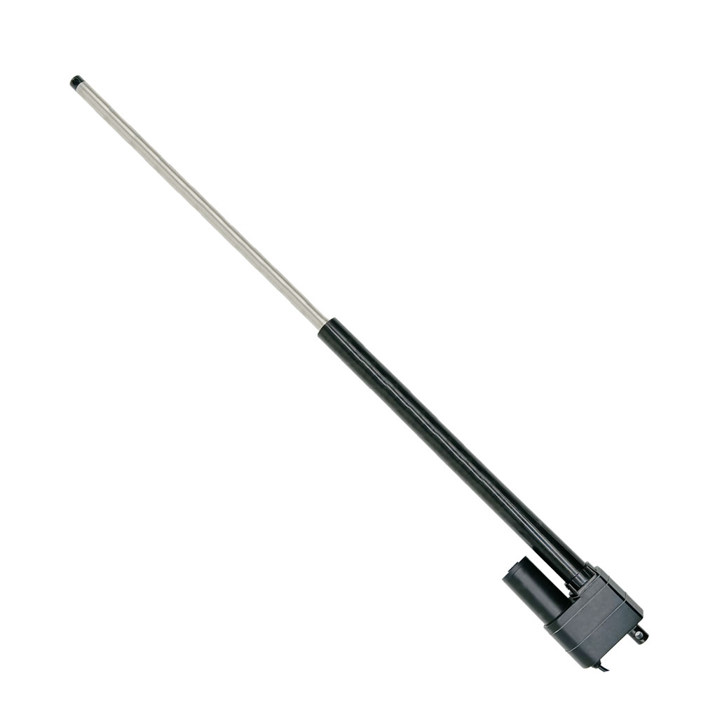
Stainless steel telescopic tube and outer tube, good corrosion resistant
Heavy duty design, high-power DC motor
Strong thrust, up to 5000N / 500 Kgs / 1100 lbs at 12mm/s
Multiple speed options, from 12 mm/second to 50 mm/second
Multiple stroke options, from 700 mm to 2000 mm
We can customize any stroke length from 700mm to 2000mm, such as 950mm, 1250mm,
1850mm and so on.
Advanced waterproof and dustproof technology
Low power consumption and low noise
Built-in clutch to protect gears and motors
Built-in motor overload and overheat protection
Built-in two limit switches, linear actuator will automatically stop when
stroke rod reaches the limit position.
Built-in Hall sensor is optional, so you can use the synchronous controller
to operate 2 linear actuators fully synchronously.
With auto-locking capability to hold load position after stopping, and no
power supply is required.
Maintenance-free
Specifications:
Optional working voltage: DC 12V, DC 24V, DC 36V or DC 48V, and 24V is the
most commonly used working voltage.
Stroke range: 28 ~ 80 inches or 700 ~ 2000 mm (If you want to view detailed information of linear actuators with different
strokes, such as detailed drawings and dimensional drawings, please click
the following link to view:
Linear Actuator C)
Optional speed: 12±2mm/s, 16±3mm/s, 20±4mm/s,
28±6mm/s, 50±10mm/s
The above is the speed at no load, and the actual working speed will
gradually slow down as the load increases.
Max Load capacity: 5000N / 500 Kgs / 1100 lbs at 12mm/s
Linear actuator can get maximum load capacity when it operates in the
vertical direction, and the pulling force is less than pushing force.
No-load current: 2~3A at 12V or 1~1.5A at 24V
Full load current: 12~20A at 12V or 6~10A at 24V
Please use a 12V/50A or 24V/25A power supply to power the two linear
actuators.
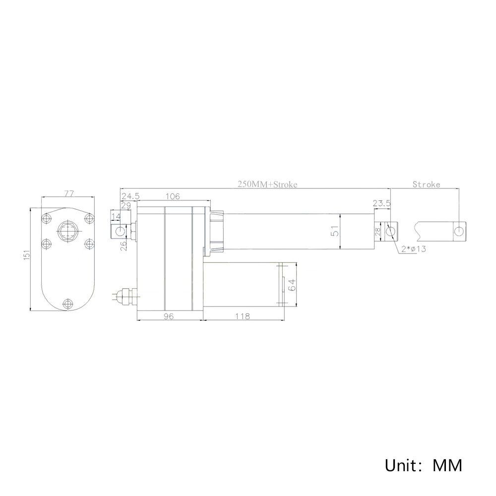
Shaft diameter: 28mm
The diameter of the mounting holes for the front and rear connectors: 13mm [0.512 in]
Housing Material: Stainless steel
Stroke Rod Material: Stainless steel
Gear Material: Steel Alloy
Motor Type: Brushed DC Motor
The orientation of the front and rear connector is default, we can rotate it
90 degrees during the production according to the customer's needs.
Duty cycle: 10%, max 5mins continuous use
Service life: approx. 35, 000 cycles
Power cable: Six-pin Plug
Cable length: 2500±10%mm [24 in], the length
can also be customized according to your specific needs.
Certifications: CE
Environment temperature: -26℃ to 85℃
Operating Noise: about 56dB~66dB (Linear actuators with different parameters
will have different noise levels.)
IP rating: IP65
Different speeds and corresponding maximum thrust:
No-load Speed
Full load Speed
Maximum Thrust
Self-locking Force
12mm/s
9mm/s
5000N / 500 kg / 1100 lbs
5500N / 550 kg / 1200 lbs
16mm/s
12mm/s
4000N / 400 kg / 880 lbs
4500N / 450 kg / 1000 lbs
20mm/s
15mm/s
3000N / 300 kg / 670 lbs
3500N / 350 kg / 790 lbs
28mm/s
20mm/s
2000N / 200 kg / 450 lbs
2500N / 250 kg / 560 lbs
50mm/s
38mm/s
1000N / 100 kg / 200 lbs
1500N / 150 kg / 340 lbs
Note:
1. The above data is the maximum load capacity that can be obtained when
each linear actuator runs in the vertical direction. The maximum load
capacity of the entire synchronous system is the sum of the maximum load
capacities of the two linear actuators. If the weight of your equipment (such as a cellar
door) is 100kg, and you want to use a linear actuator to open this door, you
need to calculate the actual force acting on the linear actuator according to
your installation method. This force is usually 2-5 times the weight of the
cellar door. If you don't know how to calculate it, please contact us for help.
2. The above is the speed at no load, and the actual working speed will
gradually slow down as the load increases. Full load speed is approximately
60-70% of No-load speed.
3. Different speeds correspond to different maximum loads. Please select the
right speed according to the speed and maximum load you need.
4. Linear actuators are not recommended for continuous operation under maximum
load, we recommend letting it work at about half of the maximum load to get a
longer working life.
5. For linear actuators with a stroke greater than 500MM, you should not
normally allow them to operate at their maximum stroke under heavy loads. If the
actual stroke you want is 600MM, we recommend that you choose a linear actuator
with a stroke of 700-800MM.
6. The maximum pull force of the linear actuator is slightly less than its
maximum thrust force.
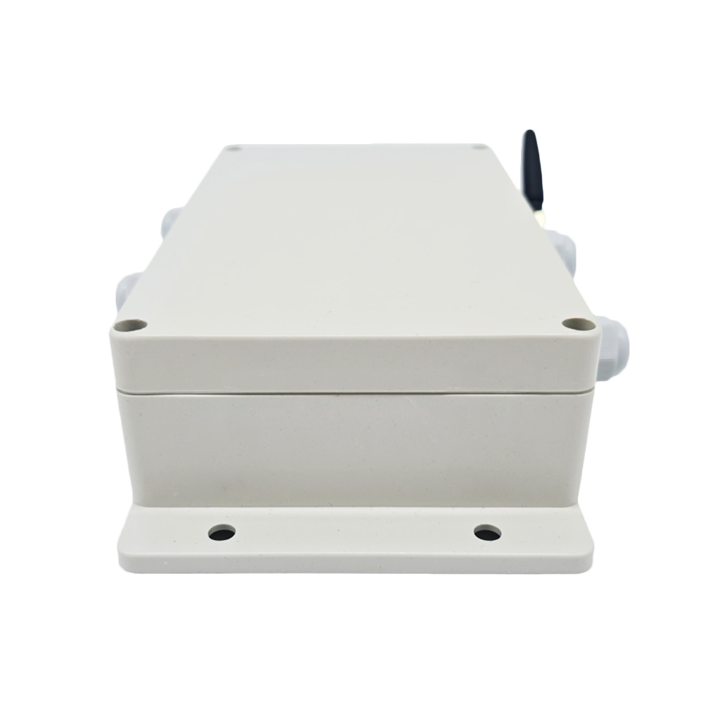
The information for synchronous controller:
Introduction:
If you want to use multiple linear actuators to raise and lower an
equipment, for example two, three or four electric actuators. Since the
high-speed DC motors in electric actuators cannot run at exactly the same
speed, so the movement speed of the electric actuator will also be
different. When multiple electric actuators work at the same time, their
actual speeds cannot be exactly the same. In this case, we can use a
synchronous controller to operate multiple linear actuators to rise or fall
synchronously. They work completely in sync without any difference.
Working principle:
If you want to use a synchronization controller to operate 2, 3 or 4 linear
actuators fully synchronously, you will need to add built-in Hall effect
sensors for each linear actuator. And when you have purchased Hall effect
sensors along with linear actuators, we will install Hall effect sensors in
the linear actuators during production for you. When 2, 3 or 4 linear
actuators are running together, Hall sensor will send Hall signals to the
synchronization controller, and the controller will adjust the running speed
of each linear actuator, so that all linear actuators run at the exact same
speed.
Feature:
It can operate two electric linear actuators C to run completely
synchronously.
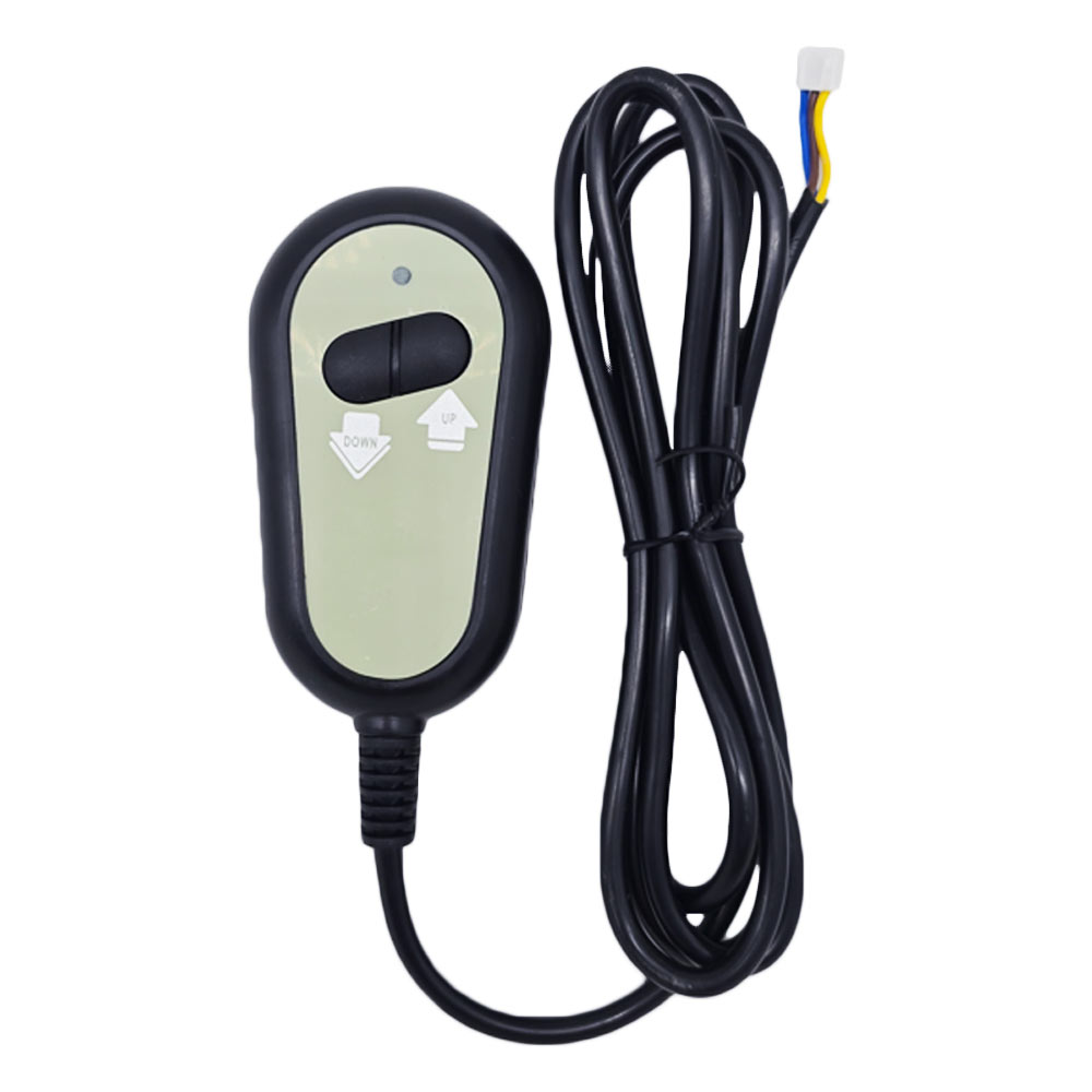
Wired control via a touch control handle.
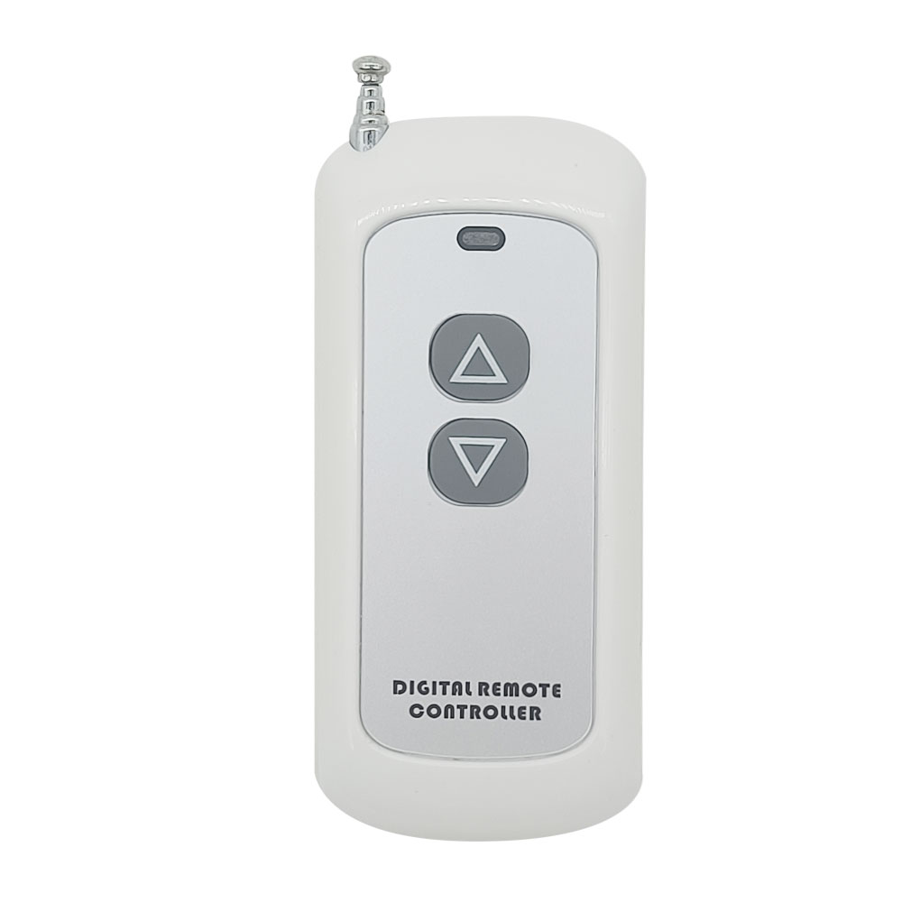
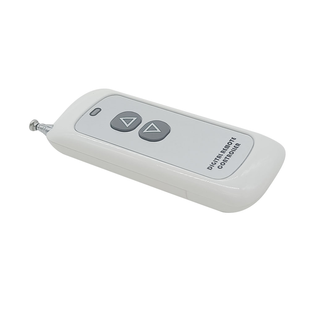
Wireless control via a remote.
The LED display on the control handle and remote control will display the
stroke position in real time.
Six touch function buttons: ▲, ▼, 1, 2, 3 and R.
Buttons ▲ and ▼ are used to operate the linear actuators extension and
retraction.
Buttons 1, 2 and 3 are used to automatically operate the linear actuators to
three pre-memorized positions.
Button R is the reset button and is used to reset the system in case of an
error.
Two selectable external control functions: manual switch function or limit
switch function, please select an external control function you need when
ordering.
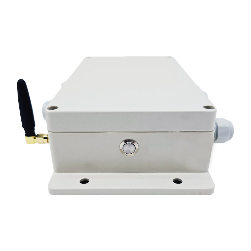
With a reset button and pairing button
When linear actuators move close to the end position, they will
automatically slow down to protect themselves.
When linear actuators are fully retracted, they will retain 1MM of travel to
protect themselves.
Parameters:
Working Voltage: 12~48 VDC, suitable for 12V or 24V linear actuator
Number of connecting linear actuators: 2
Working Frequency: 2.4 GHz
Working Distance: 10m / 30ft (theoretically)
Rated current: 25A
Two selectable control modes: Interlocking mode or Momentary mode.
Operating Temperature: -20°C ~ +70°C
Case size: 130 x 120 x 50 mm (5.1 x 4.7 x 2.0 inches) Cable length of the touch control handle: 2000±10%MM [80 in]
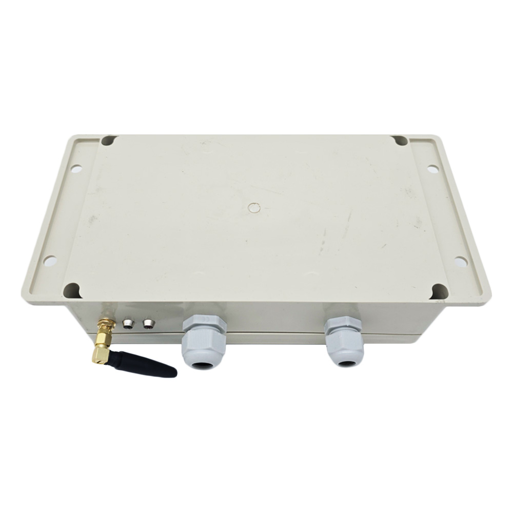
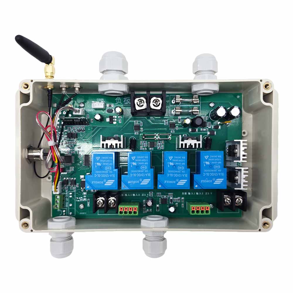
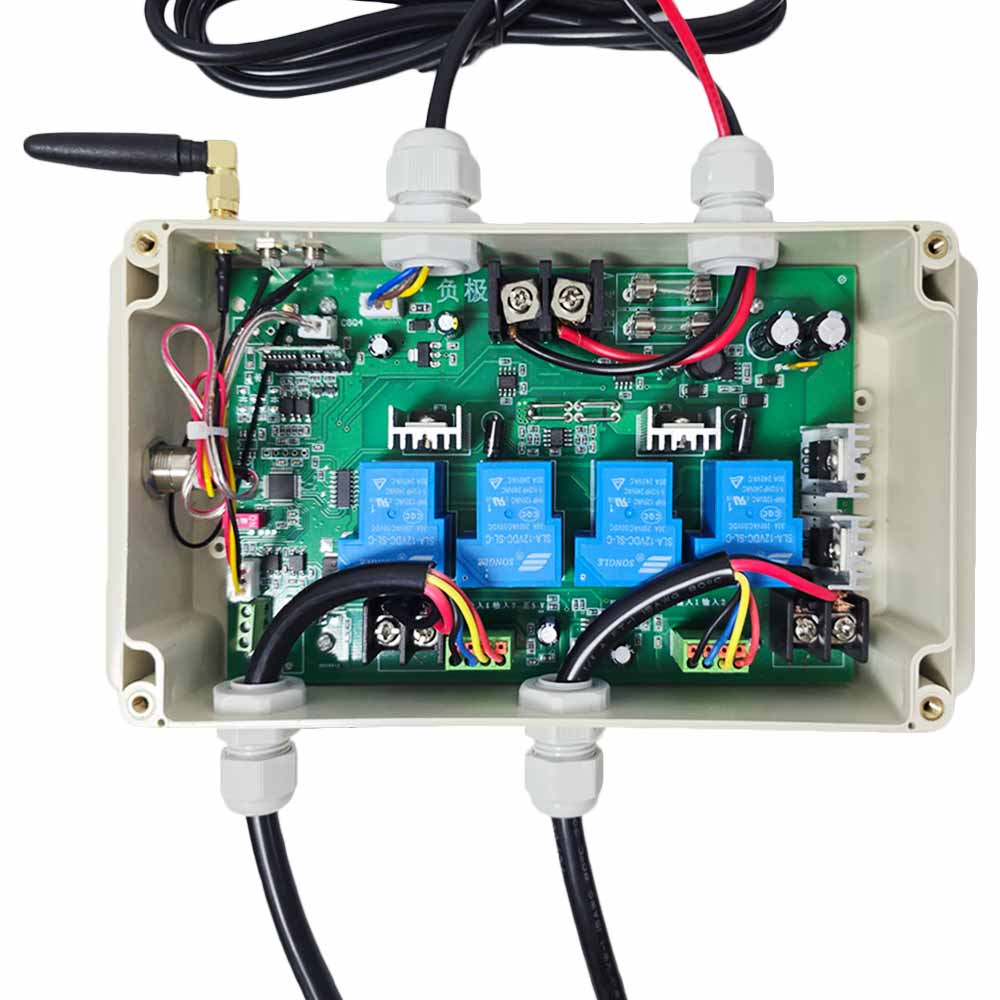
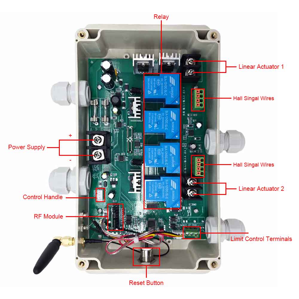
Connection:
1) Plug the touch control handle into the port Hand Set of the controller.
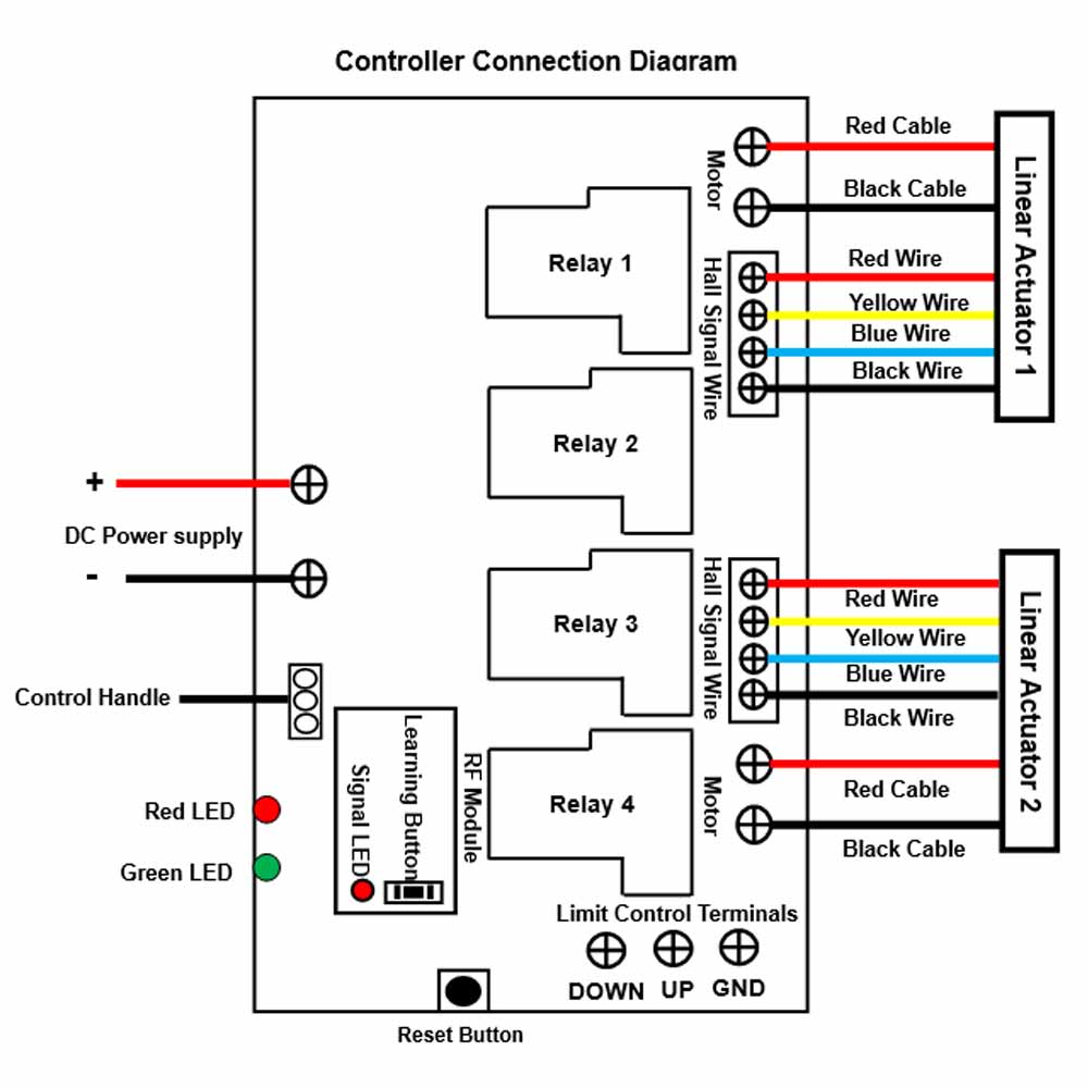
2) As shown in the diagram, plug the two terminals of the first linear
actuator into the two ports of CH1 on the controller, and plug the two
terminals of the second linear actuator into the two ports of CH2 on the
controller.
3) Connect the positive pole of DC power supply to the power terminal +
of the controller, and connect the negative pole of DC power supply to the
power terminal - of the controller.
How to set the control mode:
The controller has two selectable control modes, interlocking mode and
momentary mode. You can switch the control modes as follows:
Press the pairing button on the controller three times in a row.
Operation:
1. Operation via the touch control handle:
Attention: The handle is operated by touch control. The touch sensitivity
can be automatically calibrated when powered on for the first time. Hands
are prohibited from touching the handle when powered on to prevent
interference with the sensitivity calibration and affect the operating
sensitivity.
1) Press and hold the ▲ button of the control handle, two linear actuators
extend outward at the same time; Release the button, two linear actuators
stop at the same time.
2) Press and hold the ▼ button of the control handle, two linear actuators
retract inward at the same time; Release the button, two linear actuators
stop at the same time.
3) Press any of the button 1, 2, or 3 on the control handle, two linear
actuators will automatically move to the position memorized by that button
and then automatically stop.
Note: You will need to first memorize three positions into these three
buttons.
4) The LED display on the control handle will display the stroke position
data in real time. For example, the number 03.5 means that the linear
actuators have reached the stroke position of 35MM.
2. Operation via remote control:
2.1 When the controller is operating in momentary control mode:
1) Press and hold the button ▲ of the remote control, two linear actuators
extend out at the same time; Release the button, two linear actuators stop
at the same time.
2) Press and hold the button ▼ of the remote control, two linear actuators
retract inward at the same time; Release the button, two linear actuators
stop at the same time.
2.2 When the controller is operating in interlocking control mode:
1) Press the button ▲ of the remote control, two linear actuators extend out
at the same time, they will reach the maximum stroke at the same time and
stop automatically.
2) Press the button ▼ of the remote control, two linear actuators retract
inward at the same time, they will fully retract at the same time and stop
automatically.
3) During operation, you can press the stop button or any button of the
remote control to stop two linear actuators at the same time.
The LED display on the remote control will display the real time stroke
position data of the linear actuators. For example, if the LED display shows
UP 29.5 cm, it means the linear actuators has been extended to the stroke
position of 295mm, or if it shows DN 20.0 cm, it means the linear actuators
has been retracted to the stroke position of 200mm.
Two selectable external control functions:
The external control terminals offer a choice of two functions: manual
switch function or limit switch function. When you choose the manual switch
function, you can connect one external manual switch (such as model 0040025)
to operate the linear actuators. When you choose the limit switch function,
you can connect two external limit switches (such as model 0010010) to
automatically stop the linear actuators.
1. Manual switch function:
When you choose the manual switch function, you can connect one external
manual switch (such as model 0040025) to this controller and then operate
the linear actuators through it.
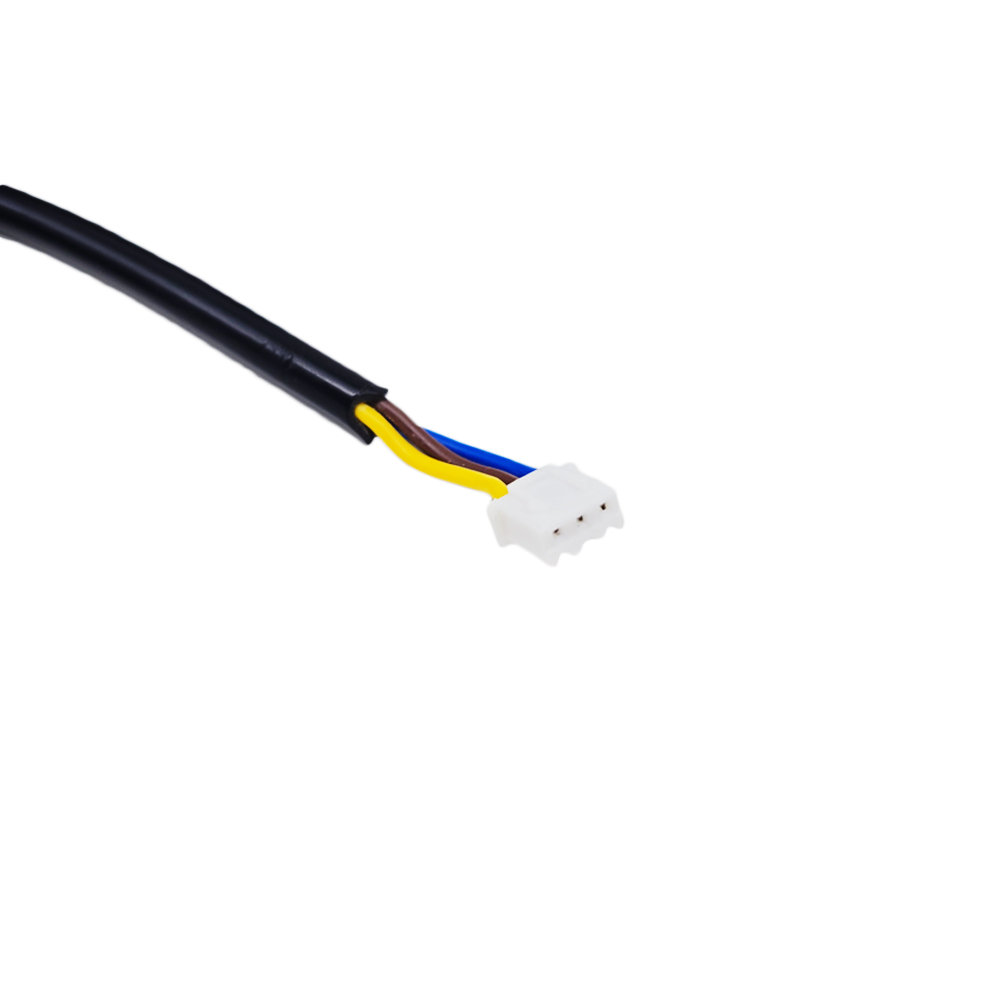
1) The manual switch has an UP button and a DOWN button, and each button has
two normally open terminals 3 and 4.
2) Connect terminals 3 and 4 of the UP button to the two terminals of UP
on the controller, and connect terminals 3 and 4 of the DOWN button to the
two terminals of DOWN on the controller.
The operation:
1) Press the UP button of the manual switch, two linear actuators extend
outward at the same time. During operation, you can also press any button of
two manual switches to stop two linear actuators at the same time.
2) Press the DOWN button of the manual switch, two linear actuators retract
inward at the same time. During operation, you can also press any button of
two manual switches to stop two linear actuators at the same time.
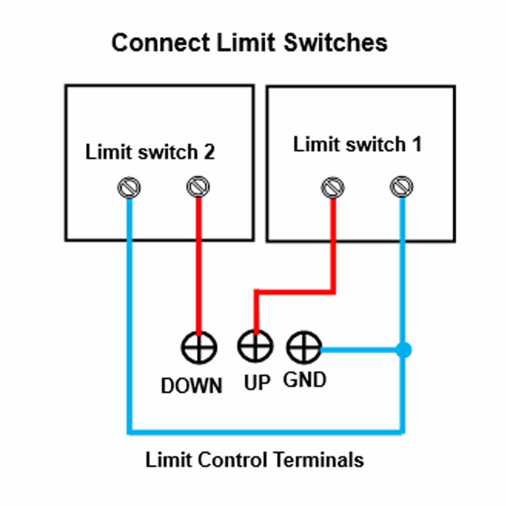
2. Limit switch function:
When you choose the limit switch function, you can connect two external
limit switches with normally open contact (such as model 0010010) to this
controller and then automatically stop the linear actuators through it.
1) You can connect two limit switches, and each limit switch has two
normally open terminals.
2) Connect two normally open terminals of a limit switch to terminals UP
and COM on the controller, connect two normally open terminals of another
limit switch to terminals DOWN and COM on the controller.
The operation:
1) When two linear actuators extend outward, if the limit switch is
triggered, it will connect two terminals UP and COM, then two linear
actuators will stop automatically.
2) When two linear actuators inward retract, if the limit switch is
triggered, it will connect two terminals DOWN and COM, then two linear
actuators will stop automatically.
How to memorize three stroke positions:
1) The controller can memorize total three stroke positions, and each button
memorizes one stroke position.
2) First operate two linear actuators to the first suitable stroke position
that you need to store, then press and hold the button 1 of the control
handle for about 5 seconds, the stroke value on the LED display will flash.
This means that the current stroke position is already stored in button 1.
3) You can continue to store the other two stroke positions into the button
2 and 3 by following the operation above.
Reset Function:
When the LED display on the control handle shows the fault code, you need to
reset the system as follows.
Reset operation: Press and hold the R button of the control handle or the Reset button on the controller, until all linear actuators are fully
retracted, and the LED display on the control handle shows "00.0", then
release the button.
Note:
1. Each linear actuator would require two mounting brackets, one to fix the
head of linear actuator and another to fix the bottom of linear actuator.
This kit does not contain fixed mounting brackets, please buy them from the
drop down menu.
2. You need to use a DC12V/50A or DC24V/25A switching power supply to power
this kit. This kit does not contain this power supply, please buy it from
the drop down menu.
Production time:
The linear actuators are the customized products, and these products are not
in stock, we need to spend 3~7 working days to produce them according to the
specified parameters in your order.
Return or Exchange:
The Linear Actuators are the customized products, we need to produce them
according to the specified parameters in your order, so that we do not accept
returns or cancel orders. If customers order unsuitable linear actuators
themselves, we also do not accept exchanges, please understand.
We can provide 3D CAD model files in STEP format for linear actuators.
Please contact us by e-mail if you need them.
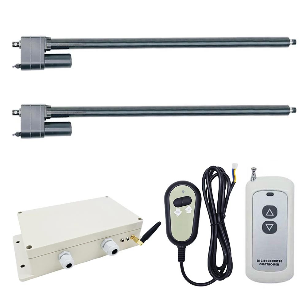
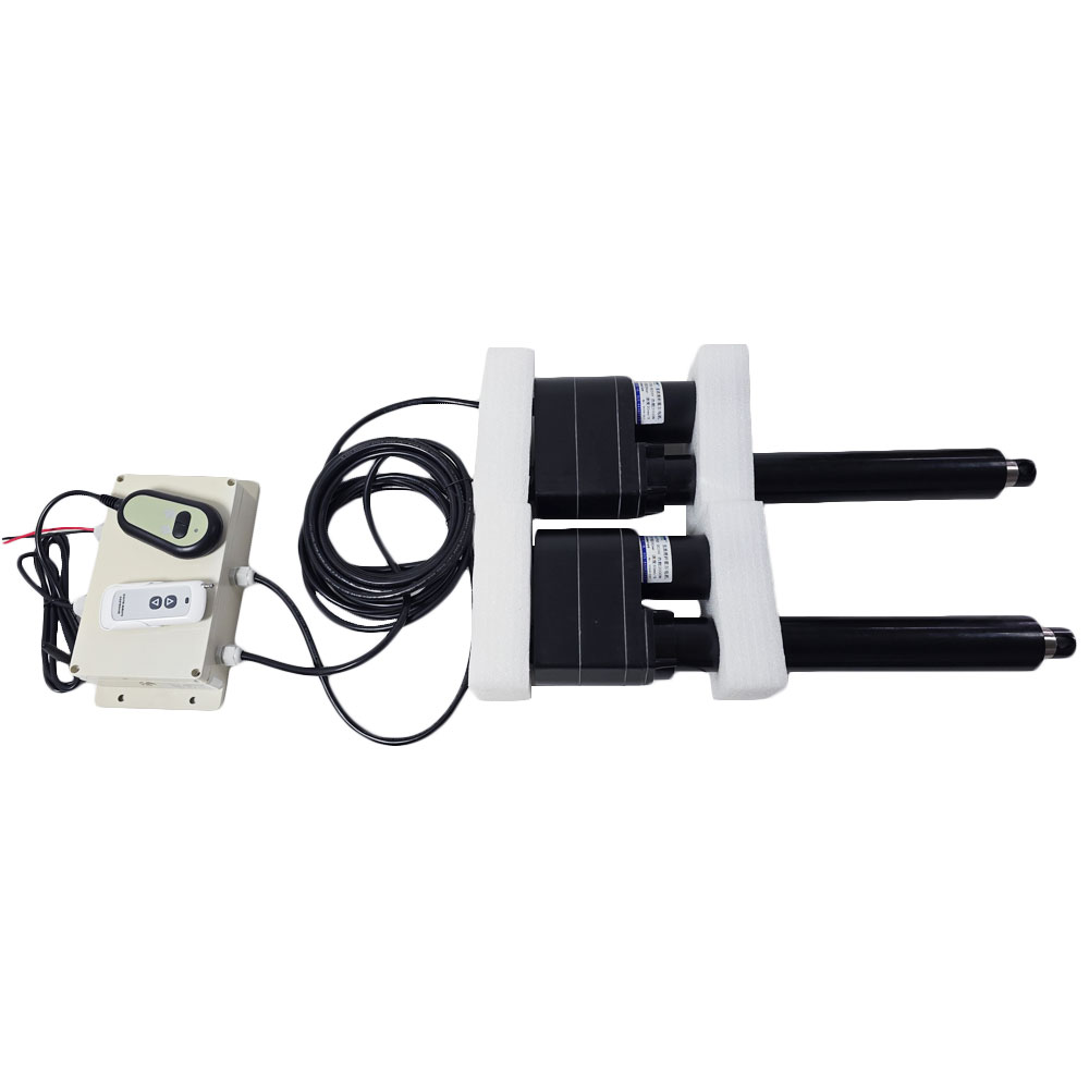
Package Include:
2 x Electric Linear Actuator C With Hall Effect Sensor
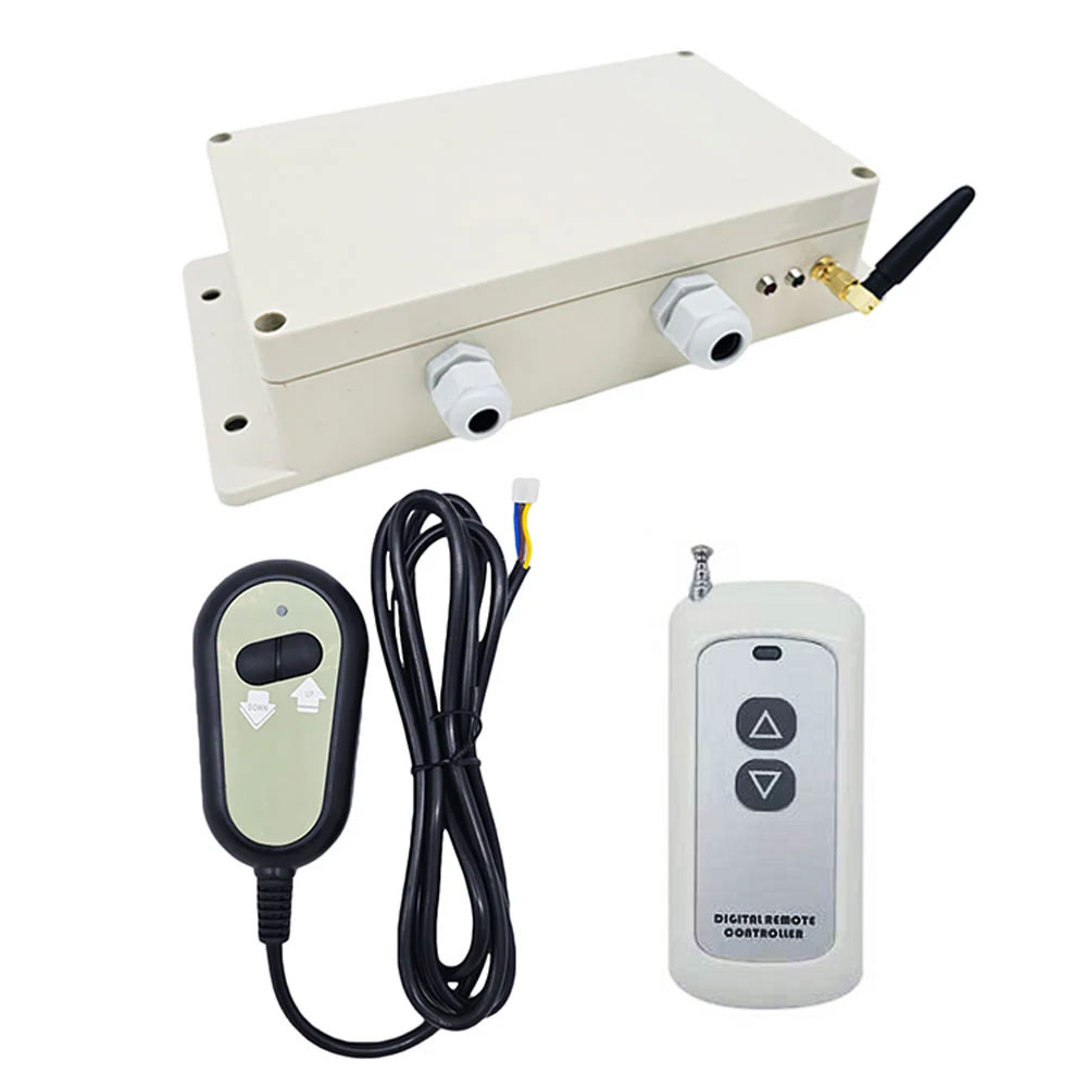
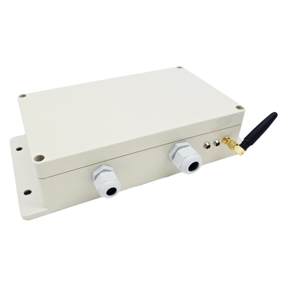
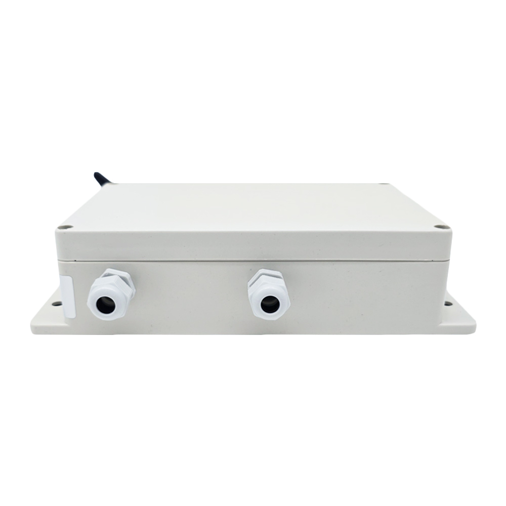
1 x Synchronous Controller (One-Control-Two, For 2 Linear Actuator C)
1 x Touch Control Handle
1 x Remote Control (CH-3)
1 x User manual