Hi, I'm Tom. Welcome to our shop,
Carymart offers you the premium rf remote control equipment.
We suggest you reading our FAQs before making your decision.
If you have any other question, please contact us.
We will reply you as soon as possible.
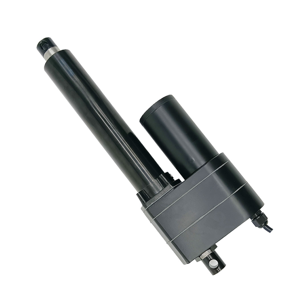
Introduction:
This linear actuator has a built-in potentiometer with three output wires
connected. When the linear actuator moves, the resistance value between the
output lines changes accordingly. In this way, we can obtain the
corresponding movement position of the linear actuator by measuring the
resistance value.
Application:
Mainly used for doors, windows, cellars, trapdoors, hatchways, solar
tracking system, medical devices, agricultural machinery, vehicles, ships,
elevator platforms, lifting tables, TV lifts, robots, cabinetries, massage
sofas, electric beds, medical chairs, and other electrical equipment. It can
open, close, push, pull, lift, and descend these devices.
It can replace hydraulic and pneumatic products to save power consumption.
Feature:
High-quality products and high-quality services
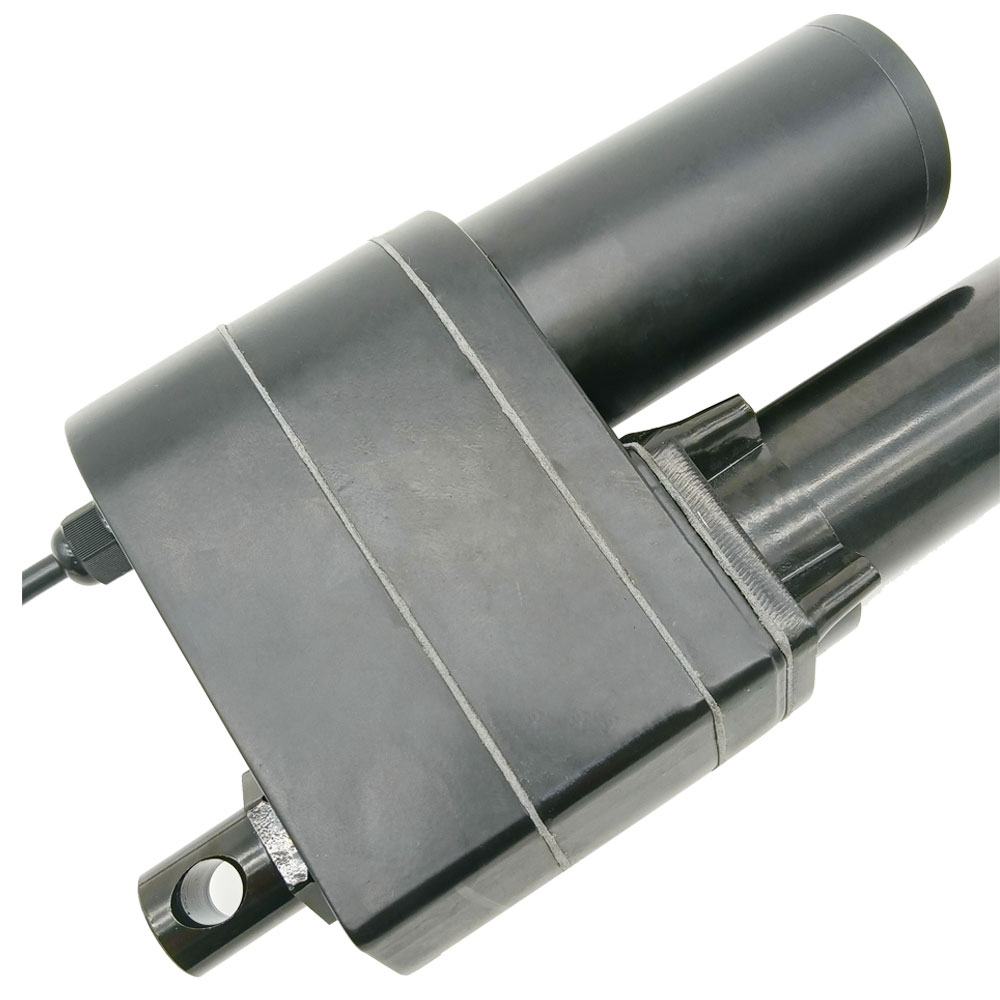
Metal housing, able to work in very harsh environments
Metal gearbox and high strength wear-resistant metal gears
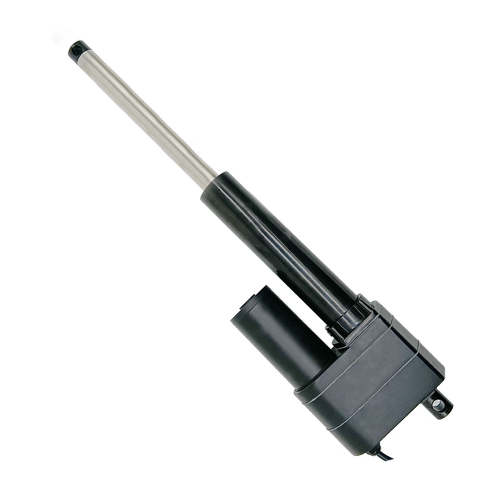
Stainless steel telescopic tube and outer tube, good corrosion resistant
Heavy duty design, high-power DC motor
Strong thrust, up to 8000N / 800 Kgs / 1800 lbs
Multiple speed options, from 5 mm/second to 50 mm/second
Multiple stroke options, from 10 mm to 2000 mm
We can customize any stroke length from 10mm to 2000mm, such as 770mm,
1250mm, 1850mm and so on.
Advanced waterproof and dustproof technology
Low power consumption and low noise
Built-in clutch to protect gears and motors
Built-in motor overload and overheat protection
Built-in two limit switches, linear actuator will automatically stop when
stroke rod reaches the limit position.
Built-in potentiometer.
Automatically lock after stopping, and no power supply is required.
Maintenance-free
Specifications:
Optional working voltage: DC 12V, DC 24V, DC 36V or DC 48V, and 24V is the
most commonly used working voltage.
Stroke range: 4 inches or 100 mm
Optional speed: 5±1mm/s, 8±2mm/s, 10±2mm/s, 12±2mm/s, 16±3mm/s, 20±4mm/s,
28±6mm/s, 50±10mm/s
The above is the speed at no load, and the actual working speed will
gradually slow down as the load increases.
Max Load capacity: 8000N / 800 Kgs / 1800 lbs at 5mm/s
Linear actuator can get maximum load capacity when it operates in the
vertical direction, and the pulling force is less than pushing force.
No-load current: 2~3A at 12V or 1~1.5A at 24V
Full load current: 12~20A at 12V or 6~10A at 24V
Please use a 12V/20A or 24V/10A power supply to power the linear actuator.
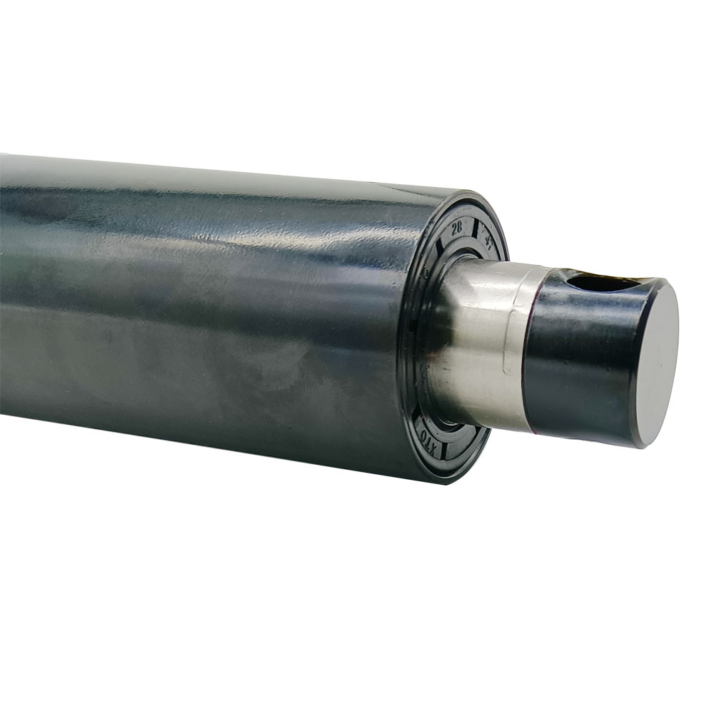
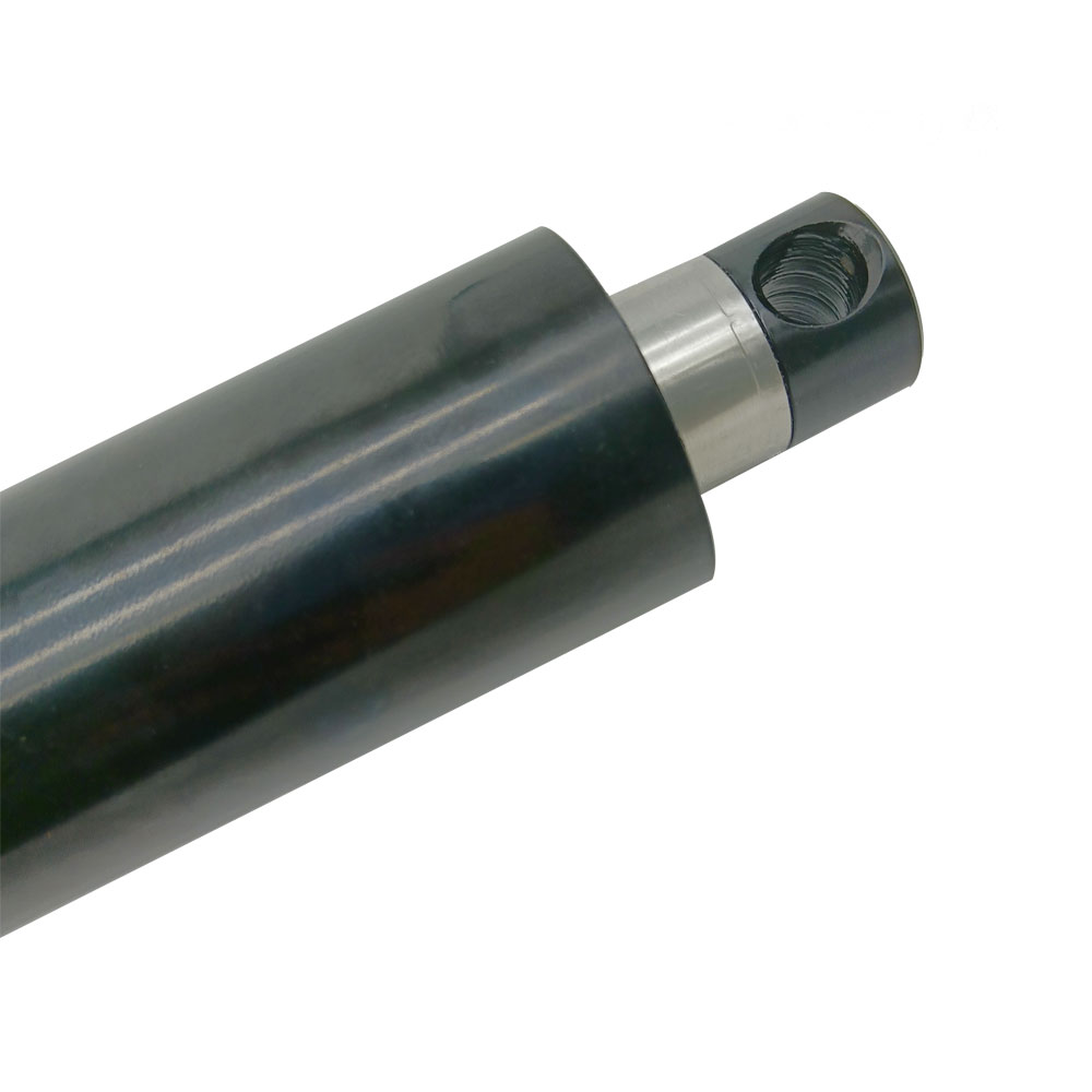
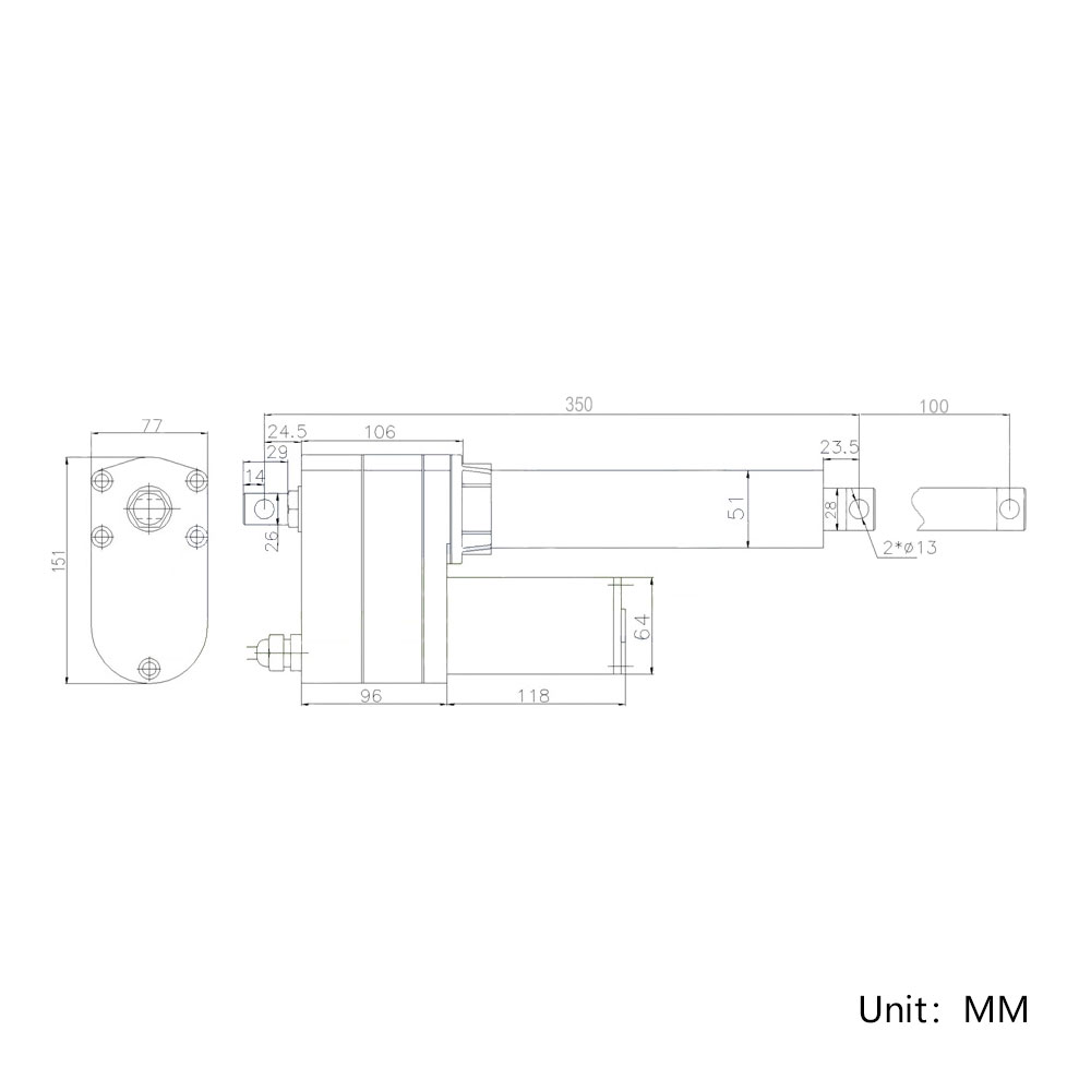
Shaft diameter: 28mm
Mounting holes diameter: 13mm [0.512 in]
Housing Material: Stainless steel
Stroke Rod Material: Stainless steel
Gear Material: Steel Alloy
Motor Type: Brushed DC Motor
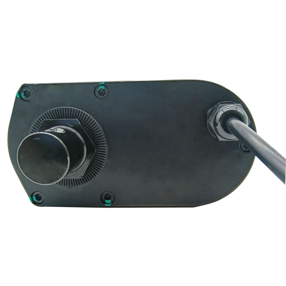
The orientation of the front and rear connector is default, we can rotate it
90 degrees during the production according to the customer's needs.
Built-in potentiometer: 10K ohms (You can specify other resistance values)
Duty Cycle: 10%, max 2mins continuous use
Service life: approx. 35, 000 cycles
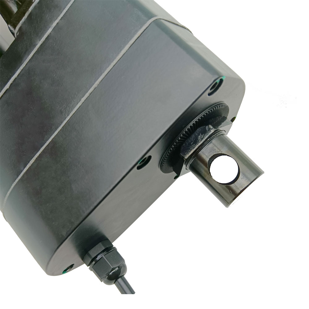
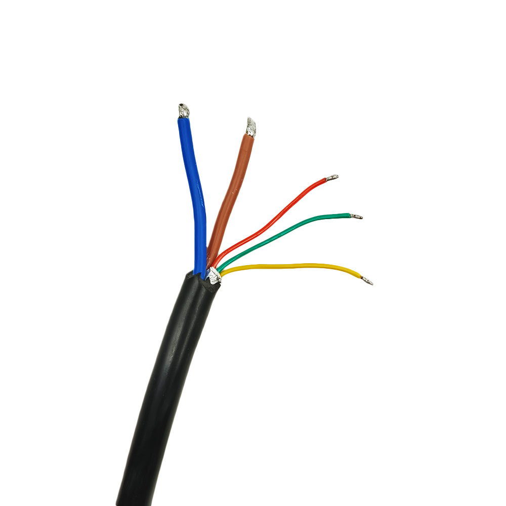
Cable: Five-core Cable (Two power wires and three potentiometer output
wires)
Cable length : 600±10%mm [20 in], the length can also be customized
according to your specific needs.
Certifications: CE
Environment temperature: -26℃ to 85℃
Operating Noise: about 56dB~66dB (Linear actuators with different parameters
will have different noise levels.)
IP rating: IP65
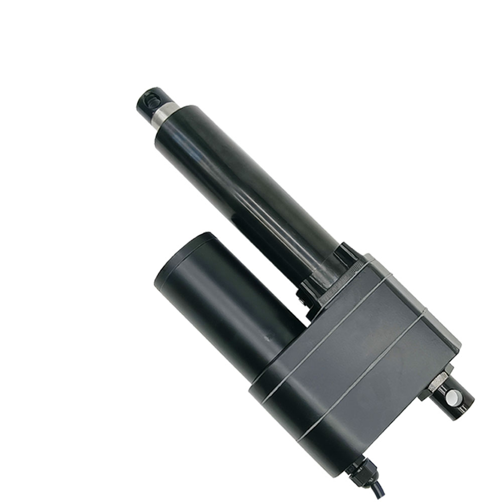
Stroke and Length (Model 0041541-2):
Stroke: 100MM.
Rretraction Length: When the linear actuator is fully retracted, the center
distance between the two mounting holes is 350MM.
Extension Length: When the linear actuator is fully extended, the center
distance between the two mounting holes is 450MM.
The linear actuator has two built-in limit switches, When the linear
actuator is fully retracted or fully extended, it will stop automatically.
We can adjust the position of the built-in limit switches during production
to meet customer-specified stroke and retraction lengths. For example,
specify the stroke length of 80MM and the retraction length of 370MM.
Note: The specified retraction length must be greater than the original
length, and the specified stroke must be less than the original stroke.
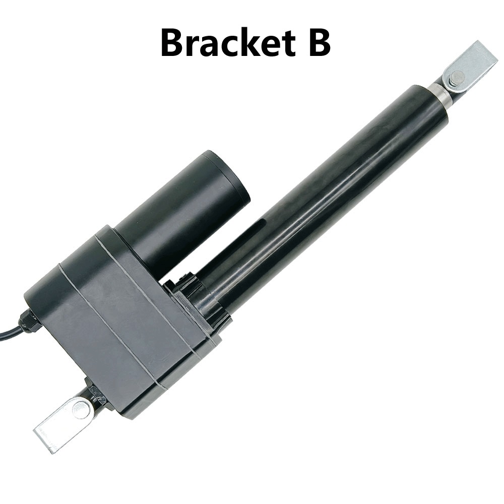
Fixed Bracket:
1. This linear actuator does not contain fixed mounting brackets, please
click
here
to purchase.
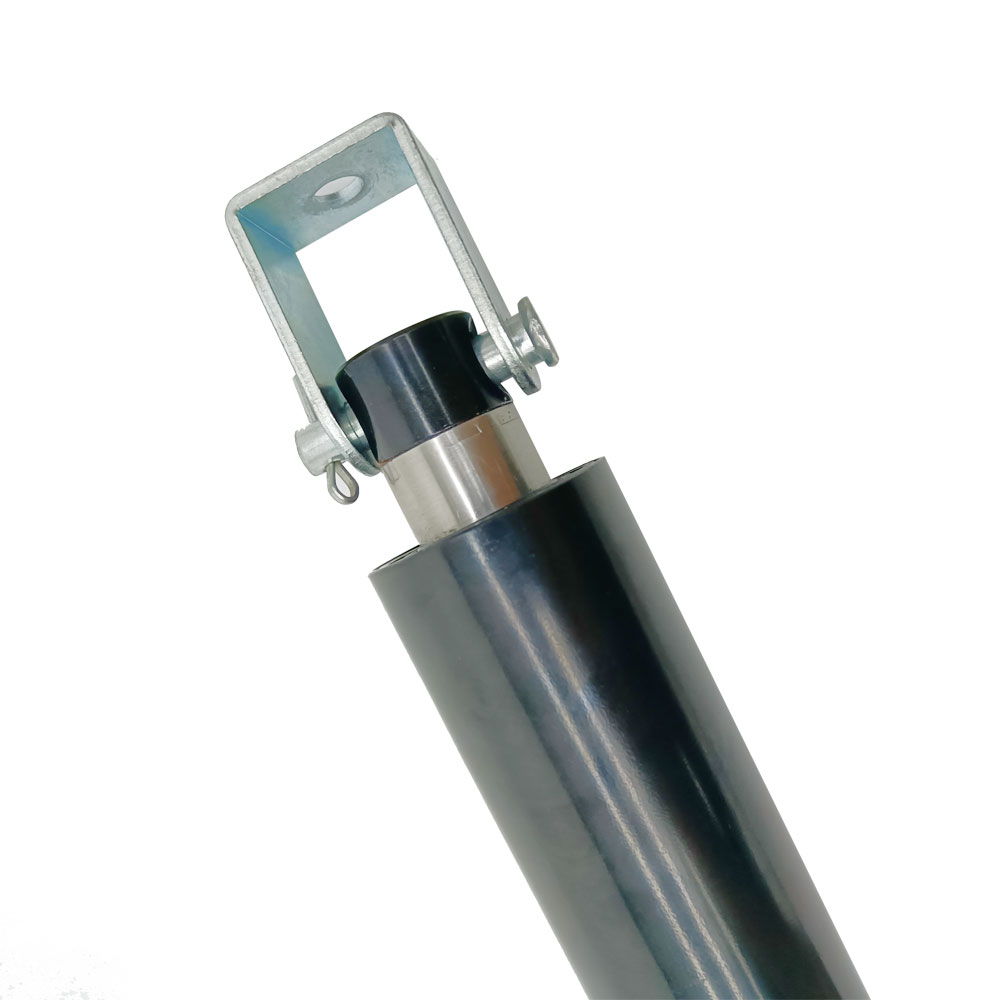
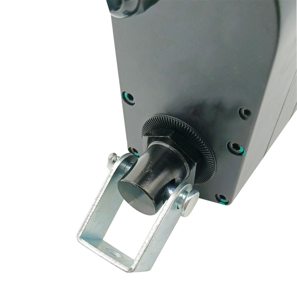
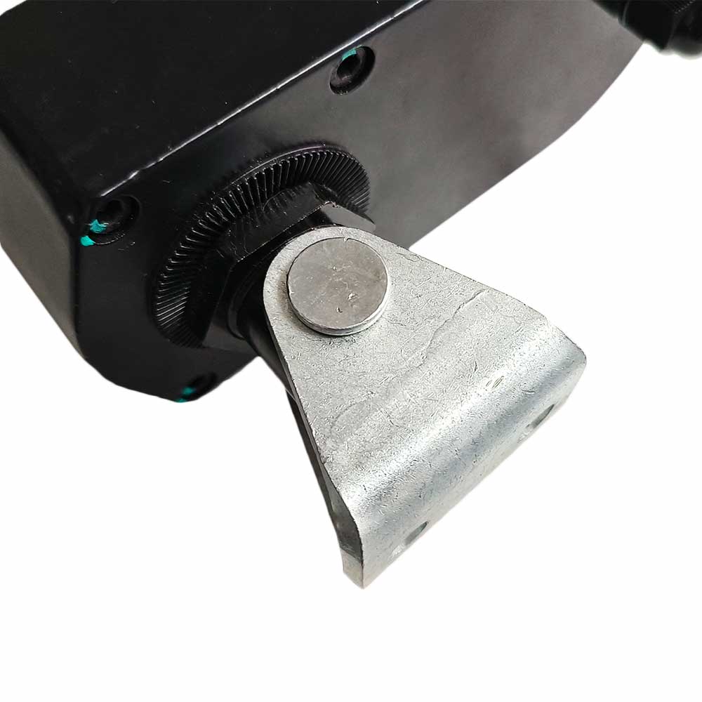
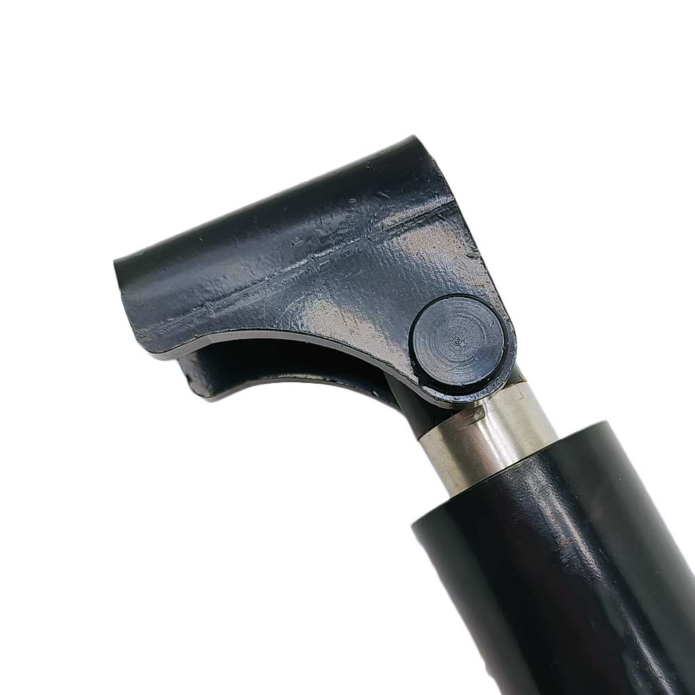
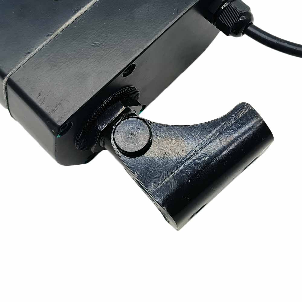
2. Each linear actuator would require two mounting brackets, one to fix the
head of linear actuator and another to fix the bottom of linear actuator.
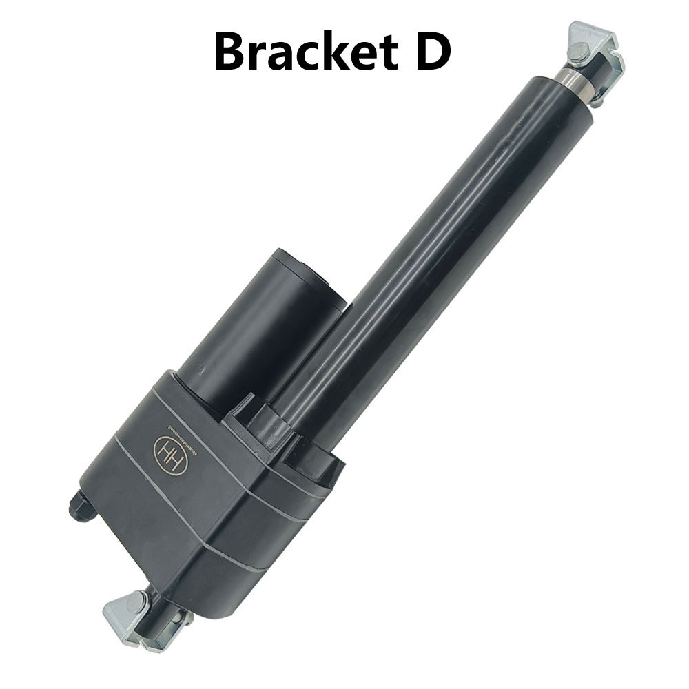
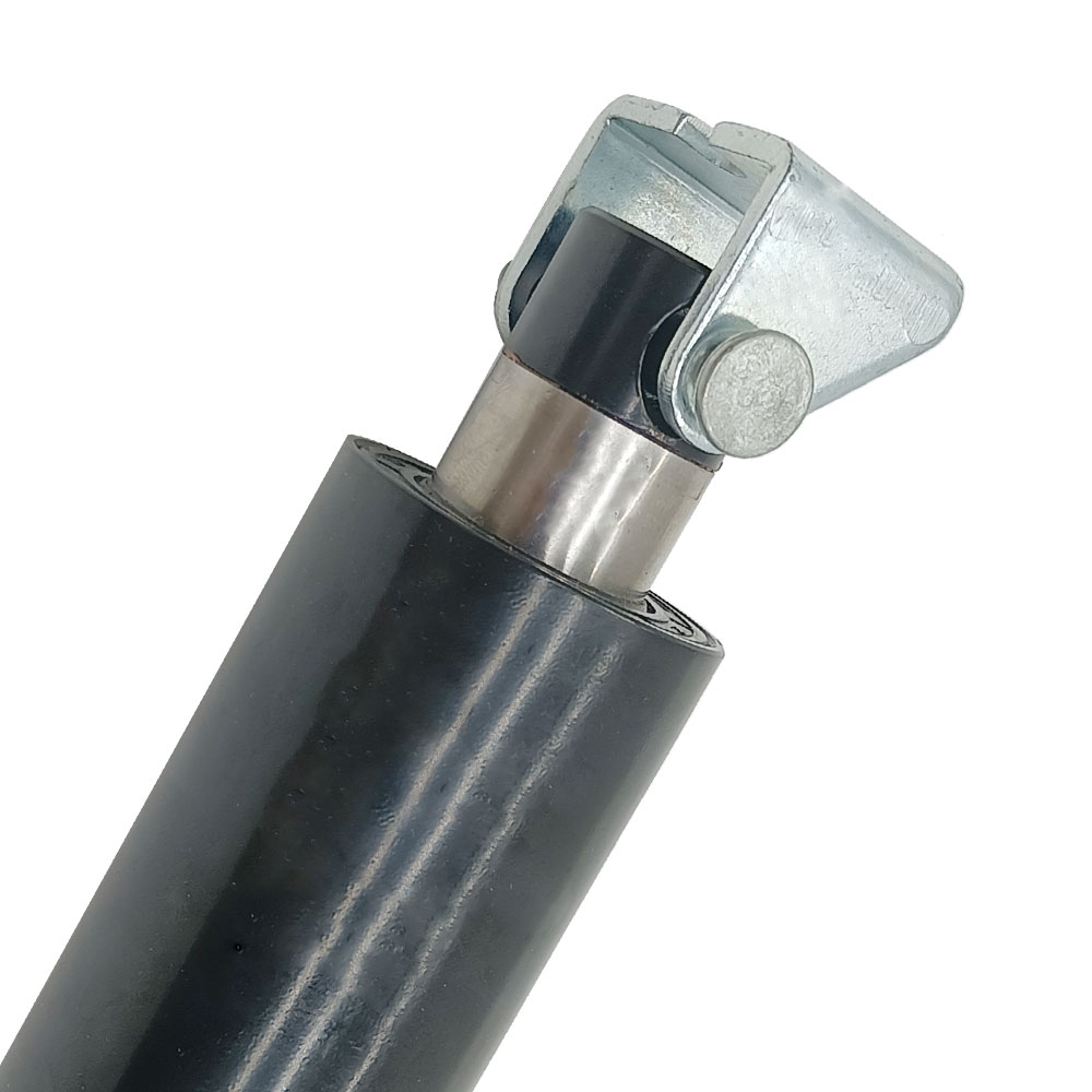
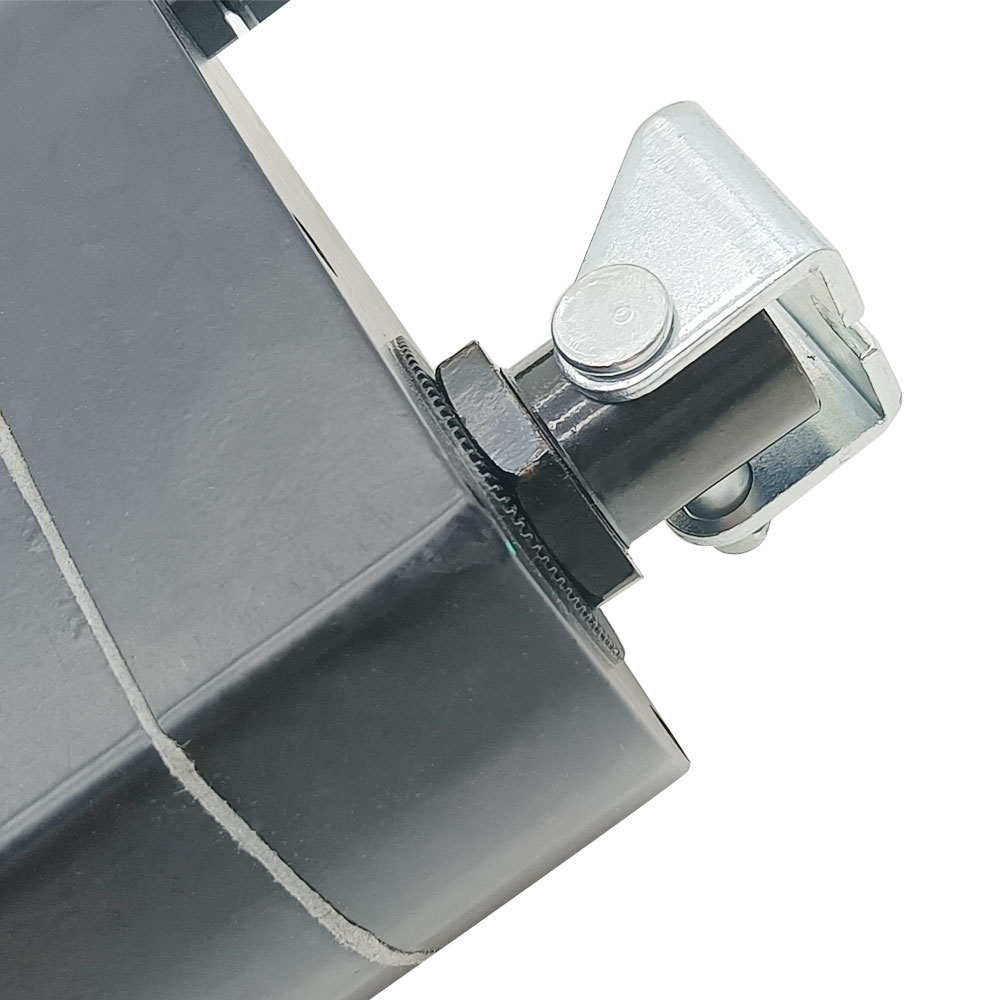
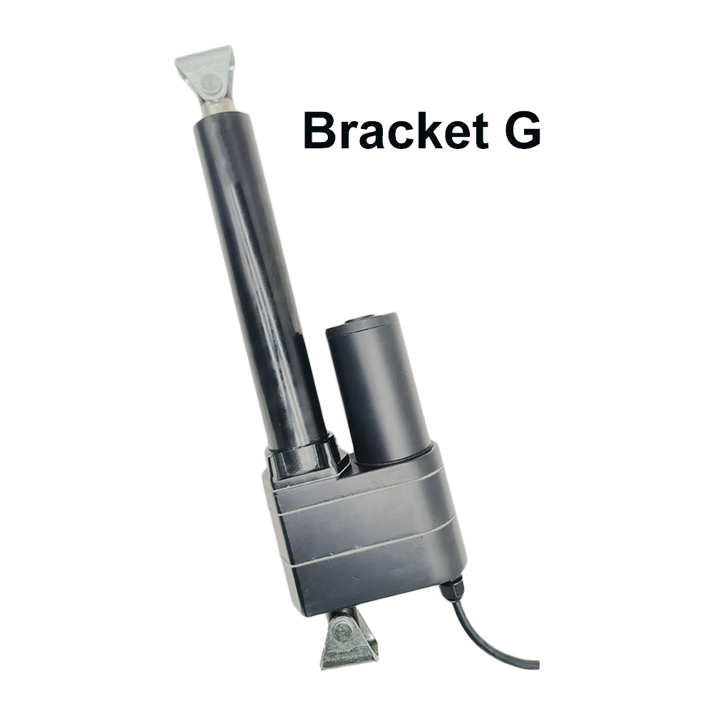
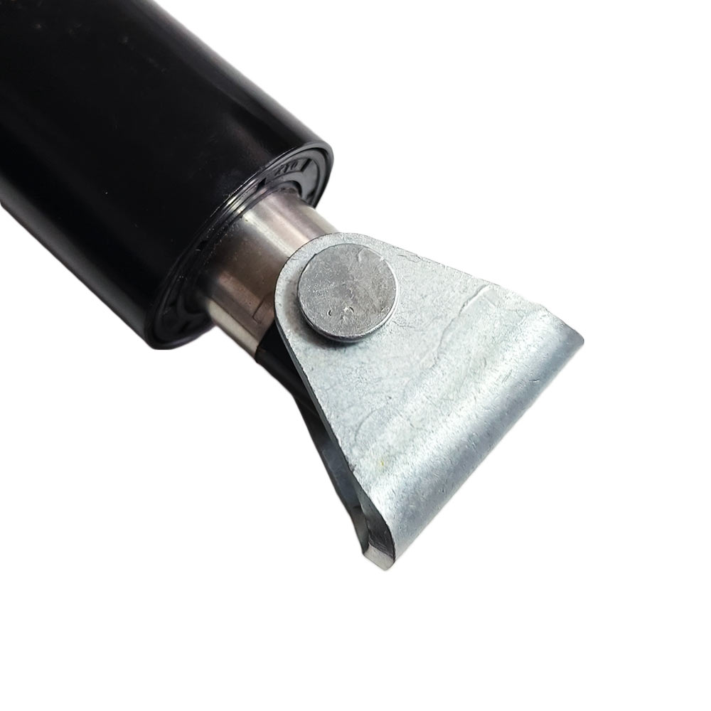
3. Compatible Mounting Brackets:
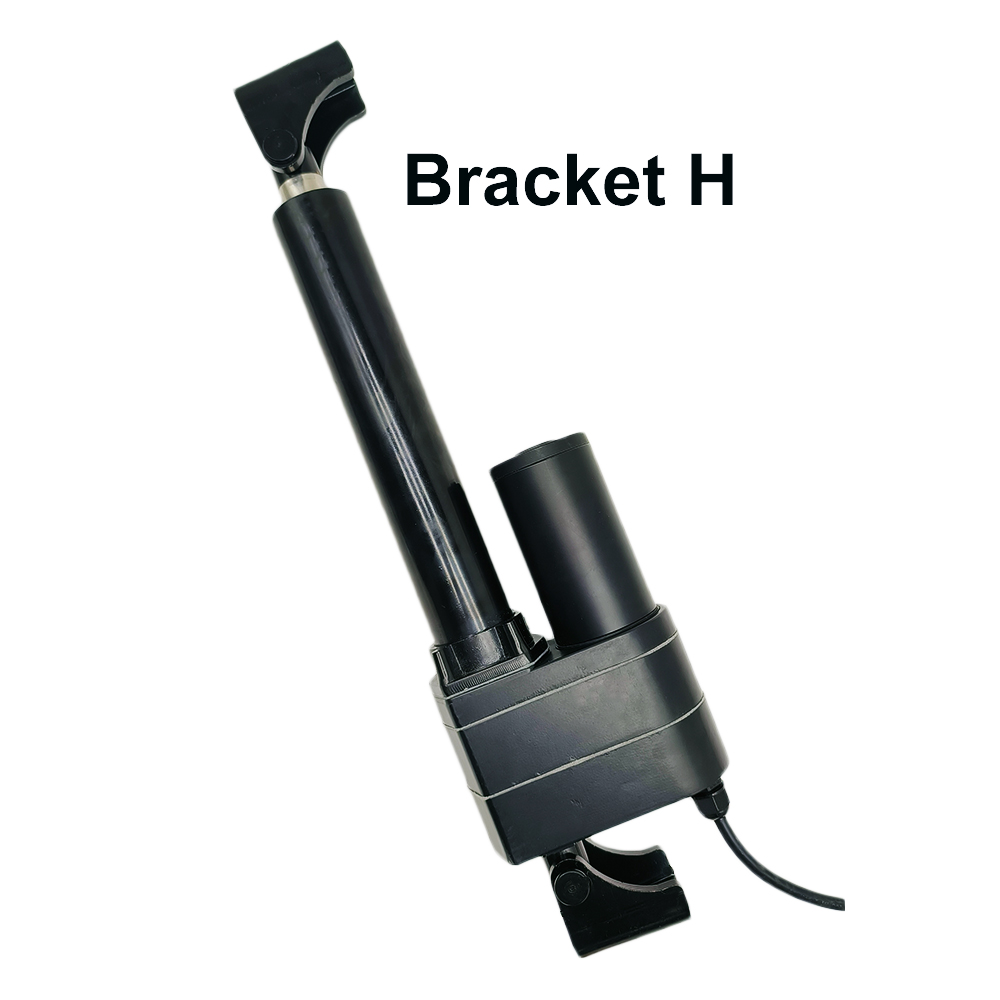
Bracket B,
Bracket D,
Bracket G
and
Bracket H
4. This linear actuator is also compatible with two flat mounting brackets:
Head Fixed Mounting Circular Disk Bracket (Model 0043075)
and
Bottom Fixed Mounting Square Plate Bracket (Model 0043076)
.
When you have purchased flat mounting bracket along with linear actuators, we will install flat mounting bracket on the linear actuator during production for you.
Operation:
The electric linear actuator has a five-core cable.
1. The brown and blue lines are two power lines of the electric linear
actuator.
When the brown power wire is connected to the positive pole of the DC power
supply and the blue power wire is connected to the negative pole of the DC
power supply, the stroke rod will extend outward; after switching the power
in the reverse direction, the stroke rod will retract inward.
2. The red, green and yellow wires are the three output wires of the
potentiometer.
The green and yellow wires are connected to the two terminals of the
potentiometer, it is a fixed resistance value.
When the linear actuator moves, the resistance value between red wire and
green wire or red wire and yellow wire changes accordingly. In this way, we
can obtain the corresponding movement position of the linear actuator by
measuring the resistance value. When the linear actuator is extended
outwards, the resistance value between red and yellow wires will decrease
accordingly, and the resistance value between red and green wires will
increase accordingly. When the linear actuator is retracted inward, the
resistance value between red and yellow wires will increase accordingly, and
the resistance value between red and green wires will decrease accordingly.
For example, a linear actuator with a stroke of 150mm and a built-in
potentiometer of 10K ohms.
When the linear actuator is fully retracted, the resistance value between
red wire and green wire is 0.4K ohms, and the resistance value between red
wire and yellow wire is 9.6K ohms.
When the linear actuator is extended to the 100mm position, the resistance
value between red wire and green wire is 3.3K ohms, and the resistance value
between red wire and yellow wire is 6.7K ohms.
When the linear actuator is fully extended, the resistance value between red
wire and green wire is 4.8K ohms, and the resistance value between red wire
and yellow wire is 5.2K ohms.
Note:
1. If you need a power supply to power linear actuator, please click
here
to purchase.
2. If you want to use external limit switches to stop linear actuator at any
position, please click
here
to purchase. How to connect limit switch? Please watch the
connection video.
3. If you want to use a remote control switch to operate linear actuator
wirelessly, please click
here
to purchase.
Different speeds and corresponding maximum thrust:
No-load Speed
Full load Speed
Maximum Thrust
Self-locking Force
5mm/s
3.5mm/s
8000N / 800 kg / 1800 lbs
8500N / 850 kg / 1900 lbs
8mm/s
6mm/s
7000N / 700 kg / 1600 lbs
7500N / 750 kg / 1700 lbs
10mm/s
7mm/s
6000N / 600 kg / 1300 lbs
6500N / 650 kg / 1500 lbs
12mm/s
9mm/s
5000N / 500 kg / 1100 lbs
5500N / 550 kg / 1200 lbs
16mm/s
12mm/s
4000N / 400 kg / 880 lbs
4500N / 450 kg / 1000 lbs
20mm/s
15mm/s
3000N / 300 kg / 670 lbs
3500N / 350 kg / 790 lbs
28mm/s
20mm/s
2000N / 200 kg / 450 lbs
2500N / 250 kg / 560 lbs
50mm/s
38mm/s
1000N / 100 kg / 200 lbs
1500N / 150 kg / 340 lbs
Note:
1. The above data is the maximum load capacity that can be obtained when the
linear actuator runs in the vertical direction. If the weight of your equipment
(such as a cellar door) is 100kg, and you want to use a linear actuator to open
this door, you need to calculate the actual force acting on the linear actuator
according to your installation method. This force is usually 2-5 times the
weight of the cellar door. If you don't know how to calculate it, please contact
us for help.
2. The above is the speed at no load, and the actual working speed will
gradually slow down as the load increases. Full load speed is approximately
60-70% of No-load speed.
3. Different speeds correspond to different maximum loads. Please select the
right speed according to the speed and maximum load you need.
4. Linear actuators are not recommended for continuous operation under maximum
load, we recommend letting it work at about half of the maximum load to get a
longer working life.
5. For linear actuators with a stroke greater than 500MM, you should not
normally allow them to operate at their maximum stroke under heavy loads. If the
actual stroke you want is 600MM, we recommend that you choose a linear actuator
with a stroke of 700-800MM.
6. The maximum pull force of the linear actuator is slightly less than its
maximum thrust force.
Production time:
The linear actuators are the customized products, and these products are not
in stock, we need to spend 3~7 working days to produce them according to the
specified parameters in your order.
Return or Exchange:
The Linear Actuators are the customized products, we need to produce them
according to the specified parameters in your order, so that we do not accept
returns or cancel orders. If customers order unsuitable linear actuators
themselves, we also do not accept exchanges, please understand.
We can provide 3D CAD model files in STEP format for linear actuators.
Please contact us by e-mail if you need them.