Hi, I'm Tom. Welcome to our shop,
Carymart offers you the premium rf remote control equipment.
We suggest you reading our FAQs before making your decision.
If you have any other question, please contact us.
We will reply you as soon as possible.
Introduction:
The linear actuator is equipped with a waterproof breather valve, which
allows air to freely flow in and out of the cylinder. When the linear
actuator is running, a pressure difference will be generated inside and
outside the cylinder, and air will flow in and out of the cylinder through
the breather valve to ensure that the pressure inside and outside the
cylinder is balanced. At the same time, the breather valve will prevent
impurities such as water and dust from entering the cylinder. In this way,
the internal components of the linear actuator are effectively protected,
ensuring that the linear actuator can operate for a long time in damp
conditions without experiencing performance degradation or damage.
Application:
It has a wide range of applications, mainly for scenes with high
requirements for noise level and waterproof level. Such as water
entertainment, on-water or on-board equipment, aquaculture, sewage treatment
systems, outdoor electric windows and doors, irrigation devices and other
water-related industrial automation equipment, household equipment and
medical equipment.
And it is mainly used for doors, windows, cellars, trapdoors, hatchways,
solar tracking system, medical devices, agricultural machinery, vehicles,
ships, elevator platforms, lifting tables, TV lifts, robots, cabinets,
massage sofas, electric beds, medical chairs, and other electrical
equipment. It can open, close, push, pull, lift, and descend these devices.
It can replace hydraulic and pneumatic products to save power consumption.
Feature:
High-quality products and high-quality services
New housing design, high working stability
Metal housing, able to work in very harsh environments
Metal gearbox, high strength wear-resistant gear
Aluminum alloy telescopic tube and outer tube, good corrosion resistant
Heavy duty design, high-power DC motor
Worm gear structure design, strong self-locking force
POM engineering plastic worm gear, low noise
Strong thrust, up to 3500N / 350 Kgs / 780 lbs.
Three speed options, 5±1mm/s, 10±2mm/s, and 16±3mm/s
Multiple stroke options, from 10 mm to 1500 mm
We can customize any stroke length from 10mm to 1500mm, such as 380mm,
750mm, 1250mm and so on.
Advanced waterproof and dustproof technology
With waterproof breather valve, ideal for use outdoors or in the rain.
Low power consumption and low noise
Built-in two limit switches, linear actuator will automatically stop when
stroke rod reaches the limit position.
Automatically lock after stopping, and no power supply is required.
Maintenance-free
Specifications:
Optional working voltage: Optional working voltage: DC 12V, DC 24V, DC 36V
or DC 48V, and 24V is the most commonly used working voltage.
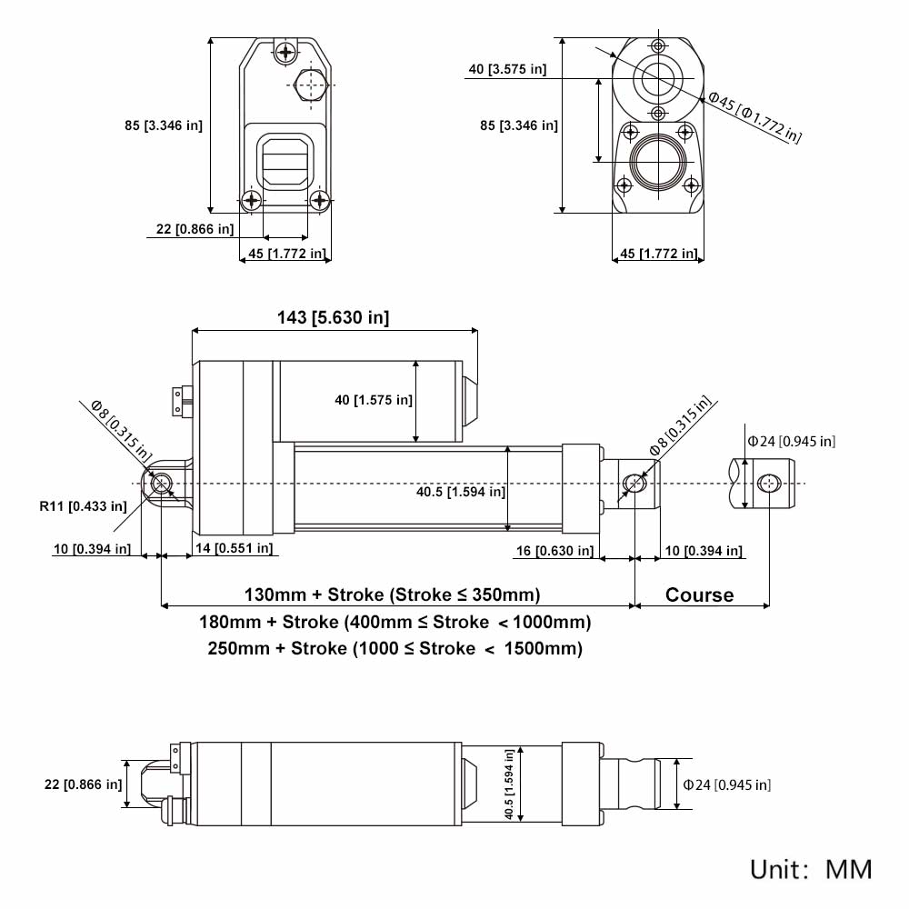
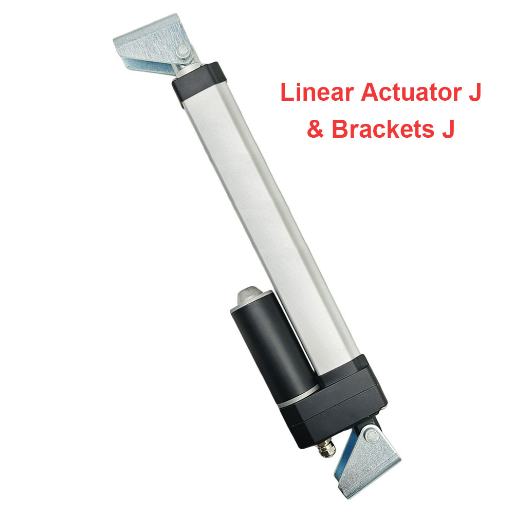
Stroke range: 0.4 ~ 60 inches or 10 ~ 1500 m (If you want to view detailed information of linear actuators with different
strokes, such as detailed drawings and dimensional drawings, please click
the following link to view:
Linear Actuator J)
Optional speed: 5±1mm/s, 10±2mm/s, 16±3mm/s
The above is the speed at no load, and the actual working speed will
gradually slow down as the load increases.
Max load capacity: 3500N / 350 Kgs / 780 lbs at 5mm/s
Linear actuator can get maximum load capacity when it operates in the
vertical direction, and the pulling force is less than pushing force.
No-load current: 0.5~1A at 12V or 0.3~0.5A at 24V
Full load current: 7A at 12V or 3.5A at 24V
Please use a 12V/10A or 24V/5A power supply to power the linear actuator.
Shaft diameter: 20mm
Mounting holes diameter: 8mm [0.315 in]
Housing material: Aluminum Alloy
Stroke rod material: Aluminum Alloy
Gear material: POM engineering plastic + Steel Alloy
Motor type: Brushed DC Motor
The front connector style can be customized: the default is an open hole
connector, which can be customized with slotted connector, internal thread
connector, etc. And you can provide drawings for customization.
The orientation of the front connector is default, we can rotate it 90
degrees during the production according to the customer's needs.
Duty cycle: 20%, max 5mins continuous use
Service life: approx. 25,000 cycles
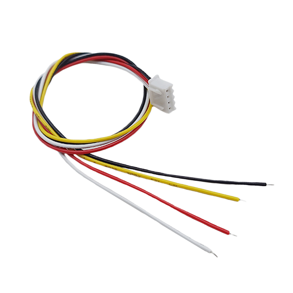
Power cable: Ordinary Two-core Wire
Cable length: 1000±10%mm [40 in], the length can also be customized
according to your specific needs.
Certifications: CE
Environment temperature: -20℃ to 80℃
Operating noise: ≤45dB (Linear actuators with different parameters will have
different noise levels.)
IP rating: IP67 (Ideal for use outdoors or in the rain, but it is not
suitable for use submerged in water.)
Different no-load speeds and corresponding maximum thrust:
No-load Speed
Full load Speed
Maximum Thrust
Self-locking Force
5mm/s
3mm/s
3500N / 350 kg / 780 lbs
5000N / 500 kg / 1100 lbs
10mm/s
5.5mm/s
2500N / 250 kg / 560 lbs
3500N / 350 kg / 780 lbs
16mm/s
8.5mm/s
2000N / 200 kg / 450 lbs
3000N / 300 kg / 670 lbs
Note:
1. The above data is the maximum load capacity that can be obtained when the
linear actuator runs in the vertical direction. If the weight of your
equipment (such as a cellar door) is 100kg, and you want to use a linear
actuator to open this door, you need to calculate the actual force acting on
the linear actuator according to your installation method. This force is
usually 2-5 times the weight of the cellar door. If you don't know how to
calculate it, please contact us for help.
2. The above is the speed at no load, and the actual working speed will
gradually slow down as the load increases. Full load speed is approximately
60-70% of No-load speed.
3. Different speeds correspond to different maximum loads. Please select the
right speed according to the speed and maximum load you need.
4. Linear actuators are not recommended for continuous operation under
maximum load, we recommend letting it work at about half of the maximum load
to get a longer working life.
5. For linear actuators with a stroke greater than 500MM, you should not
normally allow them to operate at their maximum stroke under heavy loads. If
the actual stroke you want is 600MM, we recommend that you choose a linear
actuator with a stroke of 700-800MM.
6. The maximum pull force of the linear actuator is slightly less than its
maximum thrust force.
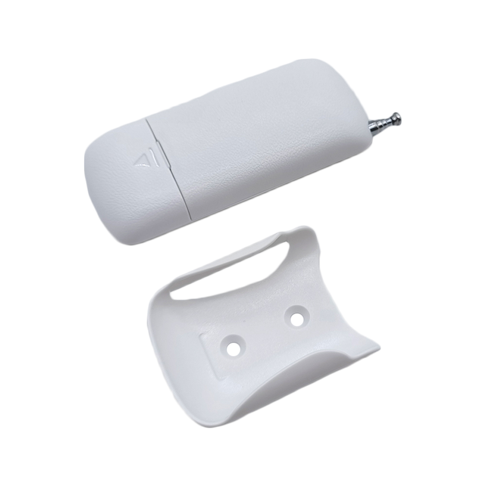
Wireless remote control information:
Application:
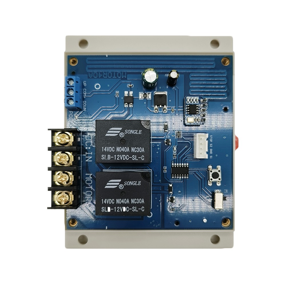
This receiver is a wireless controller for DC motor or linear actuator, it
and the transmitter form a wireless transmitter receiver system. If you connect
a DC motor to this receiver, you can operate the motor to rotate in positive or
reversal direction by using the remote control. If you connect a DC linear
actuator to this receiver, you can operate the linear actuator to extend or
retract by using the remote control. You also can connect two limit switches to
the receiver and use them to stop the motor or the linear actuator.
Features:
Wireless control, easy to install.
Suitable for DC motor or linear actuator.
Two operating voltage versions: DC 12V or 24V optional.
You can operate the motor to rotate in positive or reversal direction by using
the buttons in the receiver or by the transmitter.
You can operate the linear actuator to extend or retract by using the buttons in
the receiver or by the transmitter.
With limit control terminals: You can connect sensors, limit switches or
external devices to stop the motor or the linear actuator.
With wired control terminals: You can connect manual switches to control the
motor or linear actuator.
You can use the transmitter / remote to control the receiver from any place
within a reliable working distance.
The wireless RF signal from the transmitter can pass through walls, floors,
doors or windows, but it will lose some operating range.
The receiver has reverse power protection and over current protection built in.
The receiver only works with the selected transmitter which is matched to the
receiver.
One or more transmitters / remotes can control one or several receivers
simultaneously.
Two or more receivers may be used in the same area.
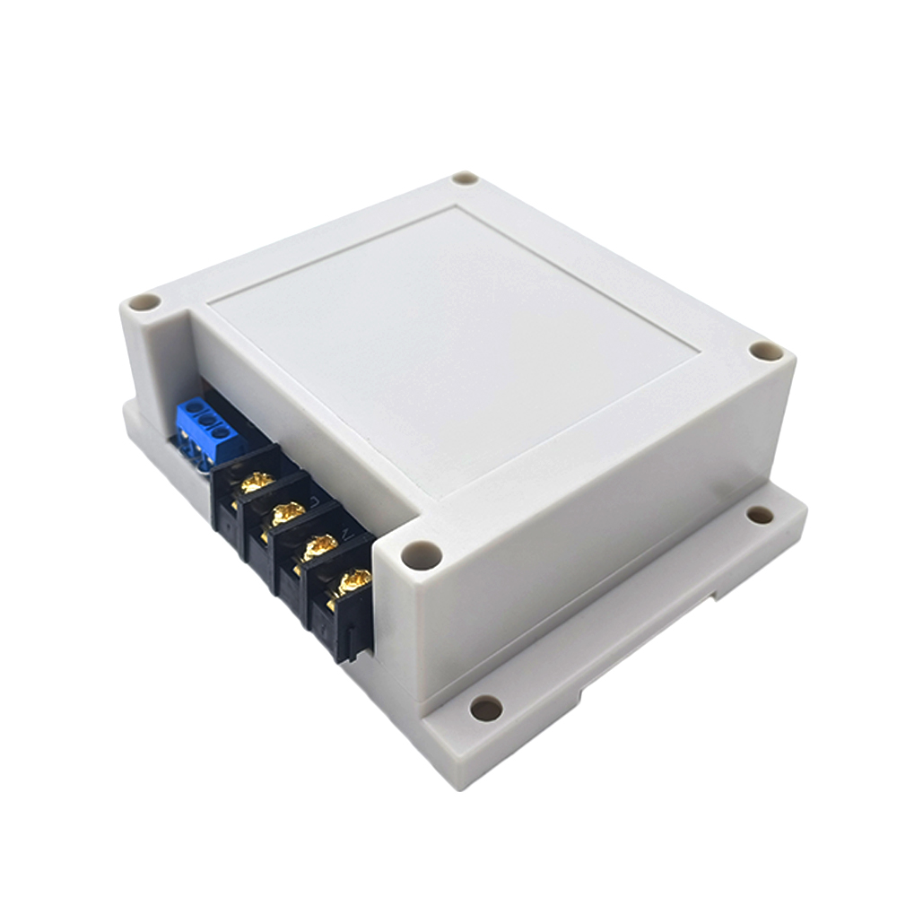
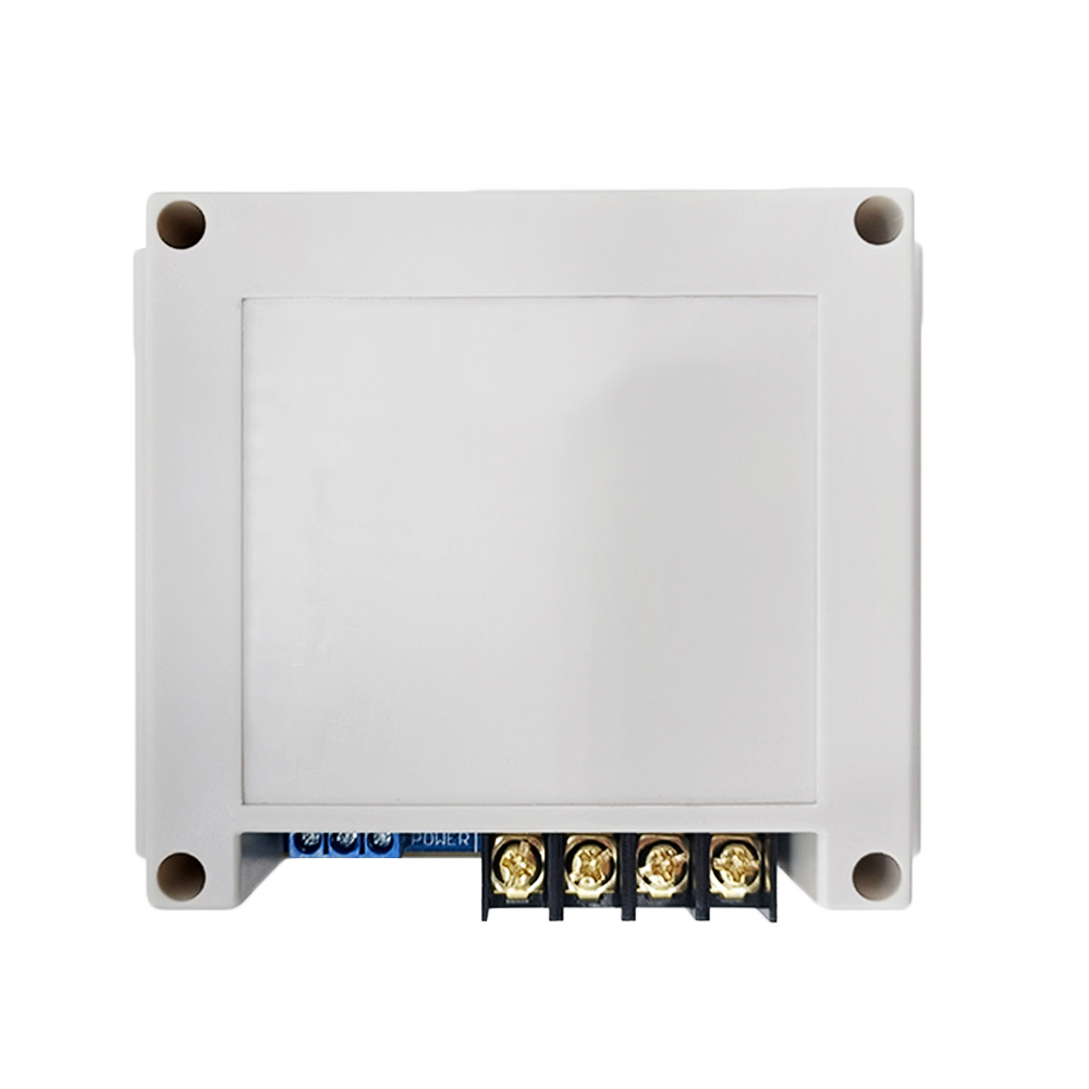
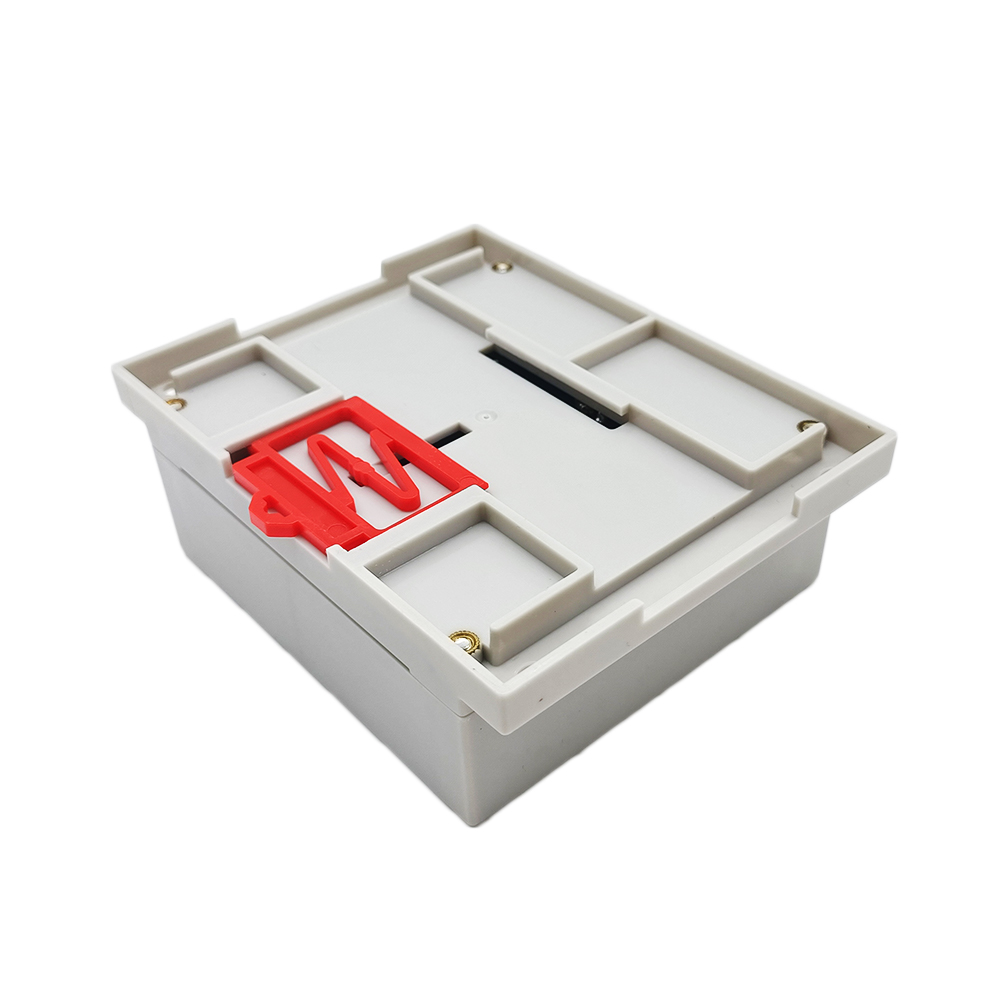
Receiver Parameters:
Model: S1PF-DC12 / S1PF-DC24
Operating Voltage: 12±1VDC (model S1PF-DC12), or 24±2VDC (model S1PF-DC24), the
operating voltage must be specified when ordering.
Output Voltage: 12VDC (model S1PF-DC12) or 24VDC (model S1PF-DC24)
Working Frequency: 433.92 MHz
Quiescent Current: ≤10mA
Rated Current: 40A, so linear actuator or motor's maximum starting current
cannot exceed 40A.
Wire range for the terminals: 22-12 AWG
2 Selectable Modes: Interlocking, Momentary
Operating Temperature: -20°C ~ +70°C
Case size: 115 x 95 x 40 mm (4.5 x 3.7 x 1.6 inches)
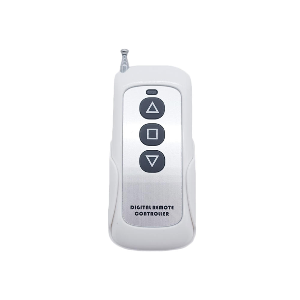
Transmitter Parameters:
Model No.: CP-3
Channel/Button: 3
Button Symbol:▲▇▼
Operating Voltage: 12V (1 x 23A -12V battery, can be used for 12 months)
Standby current: 4uA
Operating Current: 14mA
Operating Frequency: 433Mhz
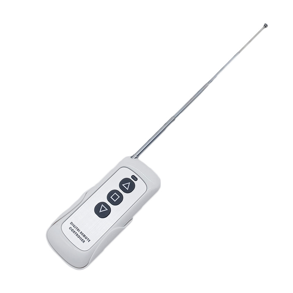
Transmitting Distance: 500m / 1500ft (theoretically)
If you stretches the telescopic antenna, it can have a further working range,
which is twice as much as it used to be.
Modulation Mode: ASK
Operating Temperature: -20 ° C to +70 ° C
Unit Size: 92 x 40 x 15 mm
Matching Transmitters:
This receiver can work with different transmitters, such as model
CWC-3L
(waterproof, 50 Meter / 150 feet),
C-2-2
or
C-3-2
(100 Meter / 300 feet),
CP-2
or
CP-3
(500 Meter / 1500 feet),
CV-2-2
(500 Meter / 1500 feet),
CG-3
(500 Meter / 1500 feet) or
CB-3-2
(1000 Meter / 3000 feet).
1) When you set the receiver in Momentary mode, it should work with two button
transmitter, such as model CP-2, C-2-2 or CV-2-2.
2) When you set the receiver in Interlocking mode, it should work with three or
four buttons transmitter, such as model CWC-3L, C-3-2, CP-3, CG-3 or CB-3-2.
Working Range:
This receiver and different transmitters form a complete set, which can
achieve different working distances. For example, when it and the
transmitter CP-3 form a complete set, the maximum working distance may reach
500 meters in an open area. When it and the transmitter CB-3-2 form a
complete set, the maximum working distance may reach 1000 meters in an open
area.
The maximum working distance is based on theoretical data without obstacles
and any RF interference. In practice, it will be hindered by trees, walls,
or other construction, and will be interfered with by other wireless
signals. Therefore, the actual working distance may not reach this maximum
distance.
The receiver equipped with an external antenna has a larger working range
than the receiver equipped with an internal antenna.
Usage:
The receiver can be used to control DC 12V / 24V motor or linear actuator.
If the power supply of those equipment is DC 12V, you should choose the
receiver with same DC 12V version; and if the power supply of those
equipment is DC 24V, you should choose the receiver with same DC 24V
version.
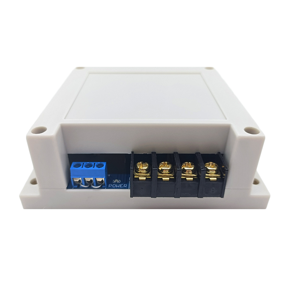
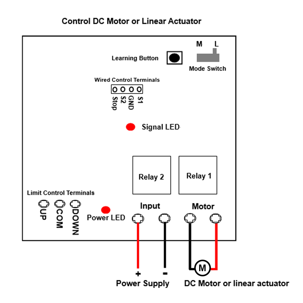
Wiring:
If you want to control a DC 12V / 24V motor or linear actuator, do as
following:
1) Connect the positive pole of DC power supply to terminal + of
Input, and connect the negative pole of DC power supply to terminal -
of Input.
2) Connect two wires of motor or linear actuator to terminals Motor,
and you can exchange these two wires to change the rotating direction of
motor or the moving direction of linear actuator.
Setting different working modes:
The receiver will be set in Interlocking mode before leaving the factory, if you
require momentary mode, please follow the following steps.
Note: Need to restart the receiver after changing the working mode.
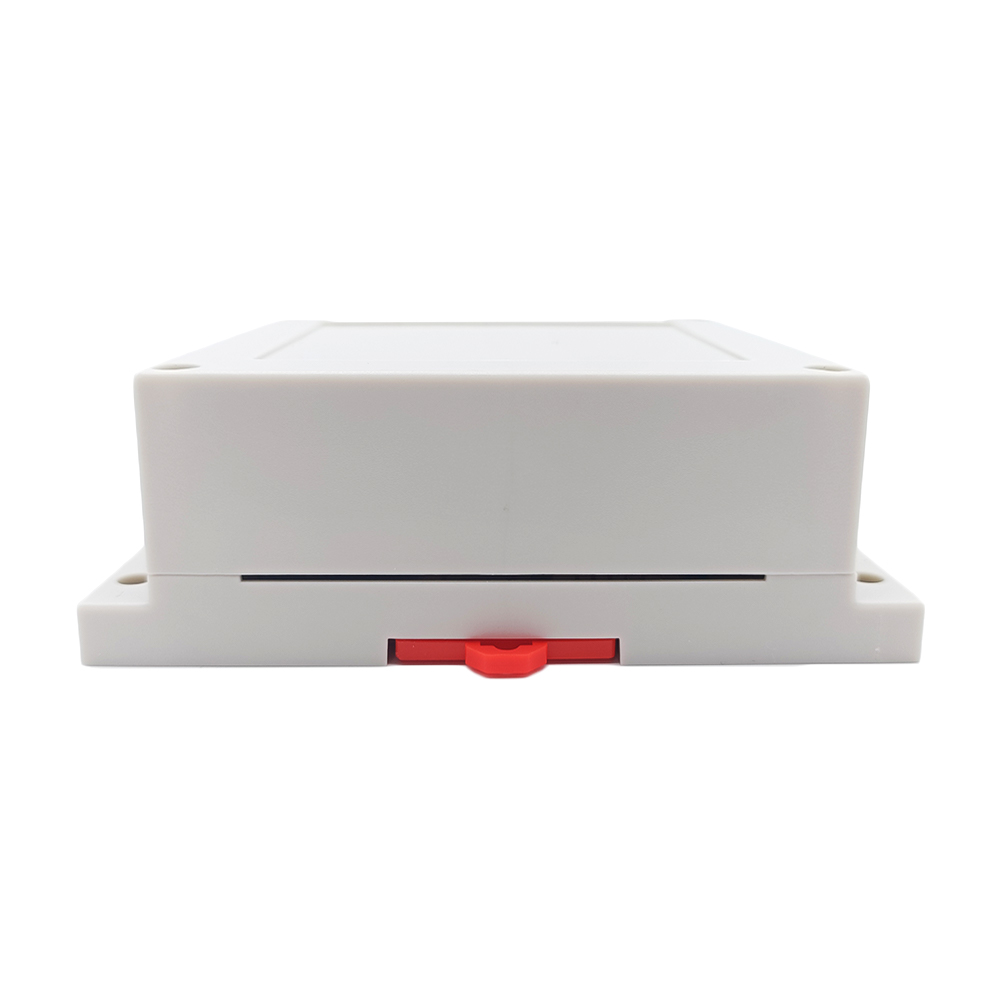
1) Setting Interlocking mode: Turn the mode switch in the receiver to
location L.
The operation by the transmitter, such as CP-3:
Press the button ▲ on the transmitter: Motor rotates in positive direction,
or linear actuator extends outward.
Press the button ▼ on the transmitter: Motor rotates in reversal direction,
or linear actuator inward retracts.
Press the button ■ on the transmitter: Motor or linear actuator stops.
2) Setting Momentary mode: Turn the mode switch in the receiver to location
M.
The operation by the transmitter, such as CP-3:
Press and hold the button ▲ on the transmitter: Motor rotates in positive
direction, or linear actuator extends outward.
Release the button ▲: Motor or linear actuator stops.
Press and hold the button ▼ on the transmitter: Motor rotates in reversal
direction, or linear actuator inward retracts.
Release the button ▼: Motor or linear actuator stops.
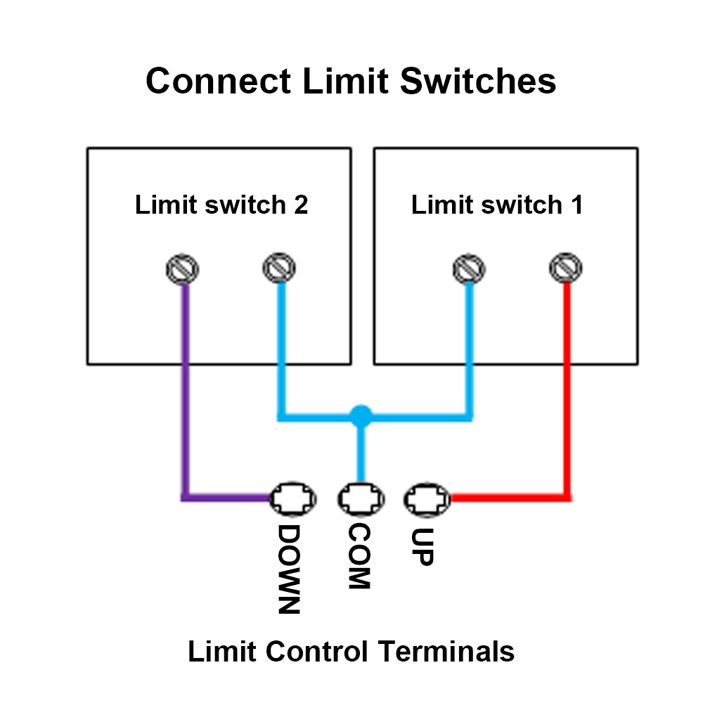
Limit control terminals:
The receiver has limit control terminals, and you can connect external
devices (with normally closed contact), such as sensors, limit switches to
limit terminals, then use them to stop the motor or the linear actuator.
For example, you can connect a normally closed limit switch to terminals COM
and UP, and connect another normally closed limit switch to terminals COM
and DOWN.
When motor rotates in positive direction, or linear actuator extends
outward, if disconnect two terminals COM and UP, the motor or linear
actuator will stop automatically.
When motor rotates in reversal direction, or linear actuator inward
retracts, if disconnect two terminals COM and DOWN, the motor or linear
actuator will stop automatically.
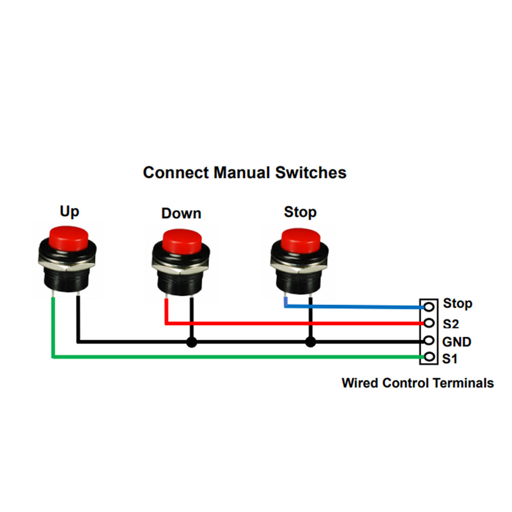
Wired control terminals:
The receiver has wired control terminals, and you can connect external
devices (with normally open contact), such as manual switches to wired
control terminals, then use them to control the motor or the linear
actuator.
For example, you can connect three manual switches to wired control
terminals STOP, S1, COM and S2 according to following wiring diagram.
1) In Interlocking mode:
When connect two terminals S1 and COM, the motor rotates in positive
direction, or the linear actuator extends outward. And when connect two
terminals STOP and COM, motor or linear actuator stops.
When connect two terminals S2 and COM, the motor rotates reversal direction,
or the linear actuator inward retracts. And when connect two terminals STOP
and COM, motor or linear actuator stops.
2) In Momentary mode:
When connect two terminals S1 and COM, the motor rotates in positive
direction, or the linear actuator extends outward. And when disconnect two
terminals S1 and COM, motor or linear actuator stops.
When connect two terminals S2 and COM, the motor rotates reversal direction,
or the linear actuator inward retracts. And when disconnect two terminals S2
and COM, motor or linear actuator stops.
Production time:
The linear actuators are the customized products, and these products are not
in stock, we need to spend 6~10 working days to produce them according to the
specified parameters in your order.
Return or Exchange:
The Linear Actuators are the customized products, we need to produce them
according to the specified parameters in your order, so that we do not
accept returns or cancel orders. If customers order unsuitable linear
actuators themselves, we also do not accept exchanges, please understand.
We can provide 3D CAD model files in STEP format for linear actuators.
Please contact us by e-mail if you need them.
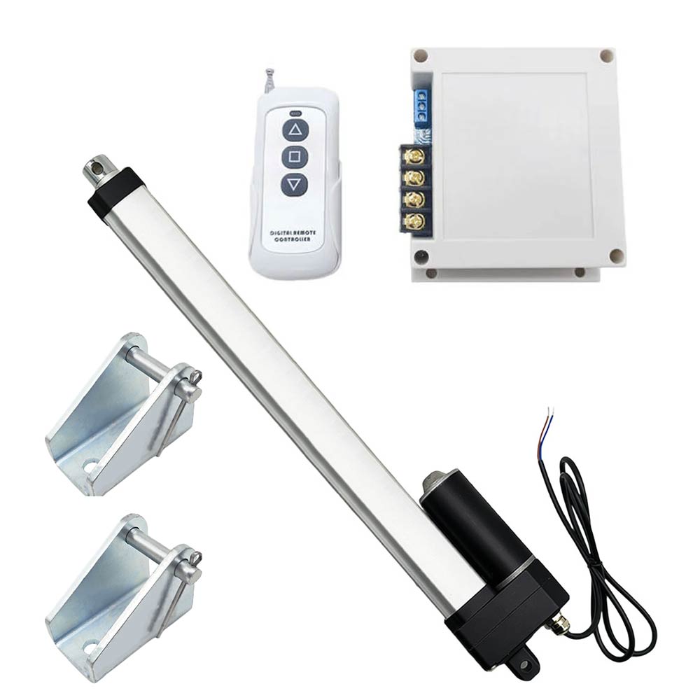
Package Include:
1 x Waterproof Linear Actuator J
1 x Receiver: S1PF-DC12 / S1PF-DC24
1 x Transmitter: CP-3
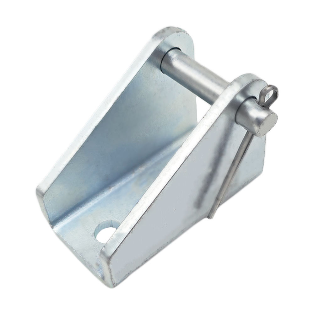
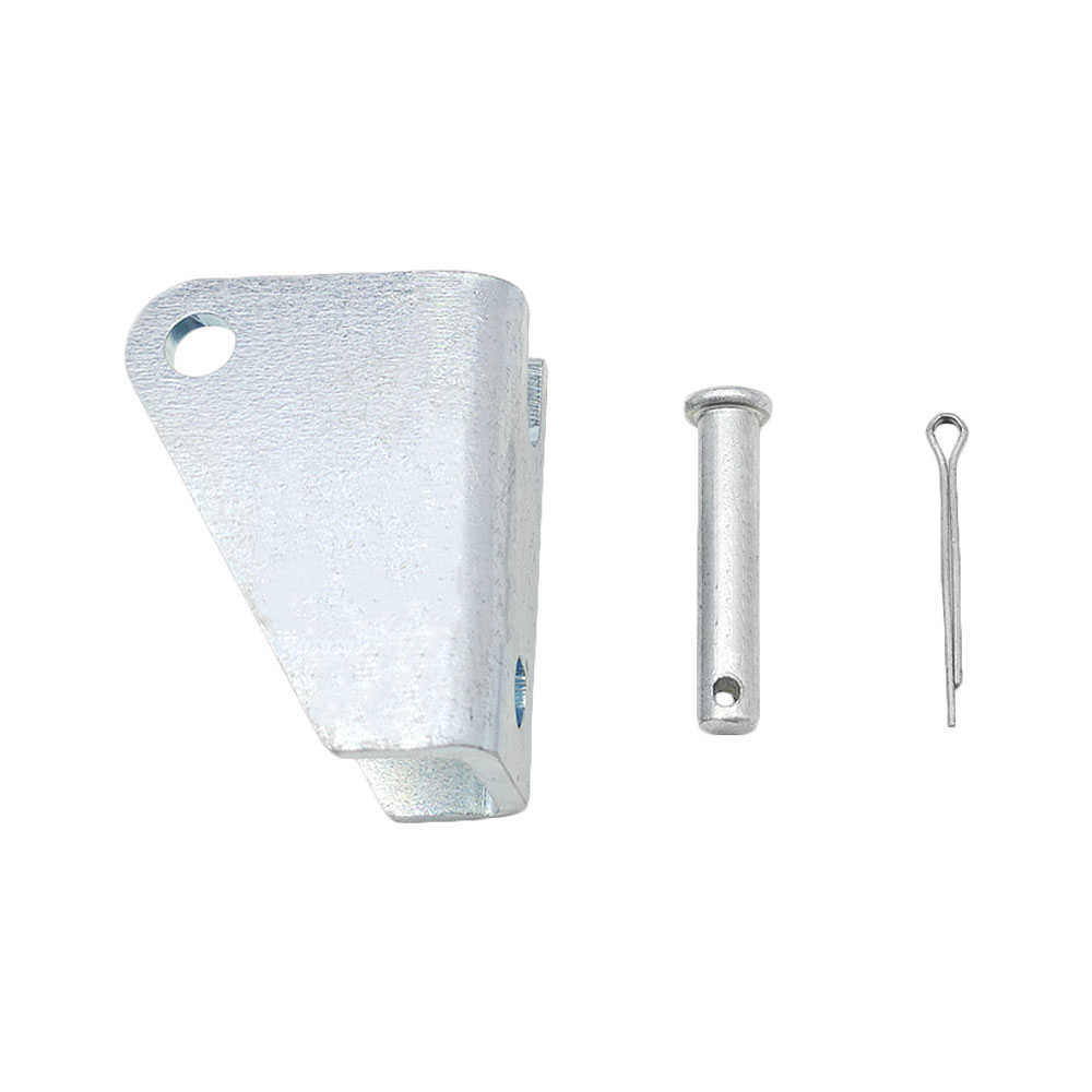
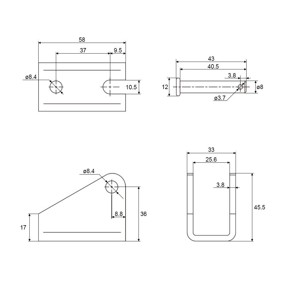
2 x Fixing Brackets J
1 x User manual